Appendix A — Exposure & Acquisition Reference Tables
Purpose
This appendix provides quick access to essential technical data frequently referenced in radiographic positioning and exposure selection.
It is designed for fast clinical lookup and supports efficient decision-making during image acquisition.
Exposure Factor Reference by Proportional Anatomy
| Proportional Anatomy Group (Examples) | Typical SID | kVp Range | mAs Range | Grid Use | Technique Notes (Technical Insights) |
|---|---|---|---|---|---|
| Distal Extremities Hands, wrists, feet, ankles |
40 in (102 cm) | 55 – 65 | 2 – 6 | No | Use short exposure times to minimize motion blur; employ small focal spot for sharp cortical detail. |
| Shoulder–Knee–Cervical Group Shoulder, humerus, knee, cervical spine |
40 in | 65 – 75 | 6 – 12 | Optional | For parts > 10 cm, add +15 % kVp or switch to grid; consider compensating filter for shoulder or knee thickness variation. |
| Hip–Femur–Pelvis–Abdomen Group Hip, femur, pelvis, lumbar spine, abdomen |
40 in | 75 – 90 | 20 – 60 | Yes | Apply anode-heel effect (anode toward head) for uniform exposure; use AEC (center + outer cells) for large field coverage. |
| Thoracic–Cervical Lateral Group Thoracic and lateral cervical spine |
40 – 48 in | 75 – 95 | 20 – 60 | Yes | Use air-gap technique (especially lateral C-spine) to reduce scatter and enhance contrast; compensate with slight mAs increase. |
| Chest (PA & Lateral) | 72 in (183 cm) | 110 – 125 | 2 – 6 | Yes | Use very short exposure (< 10 ms) to freeze motion; high kVp for long-scale contrast; grid ratio ≥ 8:1. |
| Skull–Facial–Sinus Group | 40 in | 75 – 85 | 10 – 30 | Yes | Employ tight collimation and small focal spot; reduce mAs ≈ ½ for air-filled sinuses. |
| Contrast Studies (Barium or Iodine) | 40 in | +30 % kVp above non-contrast | ¼ mAs of non-contrast | Yes | Use high kVp for penetration of dense contrast; avoid AEC over-response by using manual exposure control. |
Technique Adjustment Rules
| Situation | Adjustment |
|---|---|
| 15 % increase in kVp ≈ 2× mAs | Maintains density, changes contrast |
| 30° oblique projection | 1.5× mAs |
| 45° oblique projection | 2× mAs or +15 % kVp |
| Lateral projection | 4× mAs and +15 % kVp |
| Barium studies | +30 % kVp / ¼ mAs |
| Grid conversion (non-grid → grid) | 2× mAs or +15 % kVp |
Clinical Notes
Grid Use
Grids are designed to improve image contrast by absorbing scatter radiation before it reaches the image receptor. Scatter reduces subject contrast and can obscure low-contrast detail, especially in thick or dense body regions. Correct use of either physical or virtual grids helps maintain diagnostic image quality while optimizing radiation dose.
Physical Grid Use
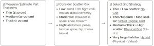
- Use a physical grid whenever part thickness exceeds 10 cm (4 in) or when scatter visibly reduces image contrast.
- Grid ratios:
- 8:1 — routine use for average adult body parts.
- 10:1 to 12:1 — for larger patients, mobile chest, or abdomen imaging where scatter is increased.
- Centering: Align the x-ray beam precisely to the grid’s center to prevent grid cut-off and ensure uniform exposure.
- SID tolerance: Adhere to the grid’s specified focal range to maintain image uniformity.
- Removal for thin parts: Remove the grid for pediatric, extremity, or thin anatomy imaging (< 10 cm) to reduce patient dose and unnecessary exposure.
- Technique compensation: When adding a grid, increase mAs or kVp per departmental grid conversion factors (e.g., +15 % kVp or 2× mAs).
Virtual (Digital) Grids & Hybrid Use
Modern digital radiography systems increasingly employ virtual grids (also called software scatter correction or grid-less scatter reduction). These post-processing algorithms estimate and suppress scatter radiation electronically, improving image contrast without requiring a physical grid.
- Mechanism: Virtual grids analyze raw image data and model scatter distribution, then subtract or correct it before image display.
- Performance: Studies show that, for many body parts (e.g., chest, abdomen, pelvis), virtual grids can produce image contrast comparable to a physical grid—often with reduced patient dose when the physical grid is eliminated and exposure factors are appropriately lowered to compensate.
- Grid ratio emulation: Some systems allow users to select a virtual grid ratio (e.g., 6:1, 10:1, 20:1) that adjusts the algorithm’s scatter-suppression strength.
- Workflow advantage: Eliminates alignment errors and simplifies mobile or trauma imaging where physical grid centering is difficult.
- Noise consideration: Unlike physical grids, virtual grids may slightly increase image noise when heavy scatter correction is applied. Use department-approved presets to balance contrast and noise.
Hybrid Use (Physical + Virtual)
In cases of very large or high-scatter patients, both a physical and virtual grid may be used together:
- The physical grid intercepts a large portion of scatter before it reaches the detector.
- The virtual grid algorithm further refines image contrast by suppressing residual scatter.
- This hybrid approach maximizes image quality for bariatric patients or high-scatter projections (e.g., lateral abdomen, cross-table spine).
- Ensure exposure technique adjustments account for grid use (typically 2× mAs for the physical grid component).
Grid Selection by Part Thickness and Scatter Level
Technique Notes
- Virtual grid: Removing the physical grid and enabling virtual correction often allows mAs reduction while maintaining contrast—verify with vendor guidance and track EI/DI.
- Hybrid (very large patients): Keep the physical grid and enable virtual correction to preserve contrast; expect higher mAs (watch heat/motion).
- Air-gap option: On some laterals (e.g., C-spine), a modest air-gap + longer SID can reduce scatter like a low-ratio grid; raise mAs to compensate.
- Tight collimation: Always reduces scatter at the source.
Clinical Notes
- For grid-less exams, remember that proper collimation and tight field size remain the most effective scatter control method.
- Always verify the virtual grid option is correctly selected on the workstation before exposure.
- Physical grids require more precise centering; virtual grids reduce positioning error but must be properly configured in software calibration.
- Document any hybrid grid use in technique protocols for reproducibility and training.
Clinical Application Notes
These reference values represent standard departmental averages.
Always verify local protocol, equipment calibration, and patient-specific considerations such as body habitus, age, or pathology.
Use these tables as a guide to maintain image quality, minimize dose, and ensure reproducible results.
