11 Filtration and Power Generation
Learning Objectives
At the end of this chapter you should be able to:
- List the main purpose for using filtration.
- Describe the effect of filtration on IR exposure and contrast.
- Recognize that filtration does not affect spatial resolution or distortion.
- Differentiate between inherent, added and total filtration.
- Explain the purpose and clinical applications of the wedge and trough compensatory filters.
Key principles of Filtration
The x-ray beam is polyenergetic. This means that the photons in the beam have many different energies. When the beam reaches the patient’s body, the photons with low energy would probably hit the patient’s skin and stop right in the skin or just under it, damaging the tissues there. These low energy photons don’t have enough energy to go through the patient’s body and deposit energy in the image receptor. Thus, it is a good idea to put something between the anode of the x-ray tube and the patient’s body to absorb these low energy photons before they ever reach the patient’s body, since they won’t do the radiograph any good anyhow. The device used to do this is called a filter.
Key Takeaways
Filtration and Beam Quality and Quantity
Since filtration removes photons from the beam, increasing the thickness of the filtration decreases the quantity, or intensity of the beam. However, because filtration preferentially removes the low energy x-rays, the decrease in quantity occurs primarily on the low energy side of the spectrum. Removing low energy photons from the beam causes the average energy of the beam to increase. Diagnostic filtration is estimated to increase the average energy (quality) of the beam by about 10%. Figure 11-1 illustrates the emission spectra of two x-ray beams.
Figure 11-1: Emission Spectra and Filtration
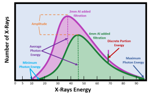
The two emission spectra above demonstrate the quality and quantity of the beam at two different filtration levels. Both beams were created with the same kVp (approximately 95 kVp as demonstrated by the maximum photon energy) and mAs.
- The beam with 2mm Al added filtration shows a shift in the minimum photon energy from zero to 10 keV.
- The beam with 4mm Al added filtration shows a further shift in the minimum photon energy from 10 keV to 15 keV, an increase in the average energy of the beam from 38 keV to 46 keV, and a decrease in amplitude, or number of photons in the beam.
A key feature of emission spectra that have undergone filtration is a non-zero minimum photon energy. Because all of the lowest energy photons are absorbed by the filtration, the first photons we detect in the beam have energies that are higher than we would get if the beam were not filtered. As the thickness of the filtration increases, the minimum photon energy moves further away from zero.
We also note that the amplitude of the graph decreases as the filtration thickness is increased. This demonstrates the reduction in the quantity or intensity of the beam. Because the filter preferentially eliminates the low energy photons, we see a bigger decrease on the low energy side of the graph. But absorption of photons by the filter occurs to some extent at all energy levels.
When we eliminate the low energy photons in the beam, the average energy (quality) of the beam increases. This is like a course where your lowest 3 quiz scores are dropped from your course grade. Because we preferentially eliminated the low scores, your average grade in the class goes up.
Notice that changing the level of filtration does not change the energy of the discrete portion of the graph. Do you remember what controls the energy of the discrete portion of the graph? If not, take a look at Ch. 2 to jog your memory. Changing filtration levels also does not change the maximum photon energy. What determines the maximum photon energy of the beam? Did you say kVp? That’s right! See Figure 11-2 for a recap of the impact of filtration on beam quality and quantity.
Figure 11-2: Filtration and Beam Quality and Quantity
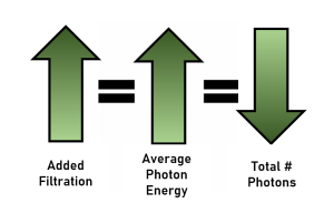
As the amount of filtration increases,
- The average photon energy in the beam, i.e. the beam quality, increases.
- The total number of photons in the beam, i.e. the beam quantity, decreases.
Sources of Filtration
There are two sources of filtration, inherent and added.
Inherent Filtration
Inherent filtration is present because of the design of the x-ray tube. It is a part of the tube and cannot be eliminated. The x-ray tube has a leaded glass covering or envelope around it. The glass has a thinner spot in it called the window. This window is positioned under the anode. The x-ray photons have to pass through the window after they leave the anode and are traveling through space to the patient. As the x-ray photons pass through this window, lower energy photons are absorbed by the leaded glass. Thus the window of the x-ray tube removes or filters some of the photons from the beam.
As an x-ray tube ages, a layer of vaporized tungsten from heating of the filament and the anode collects on the inside of the glass envelope. This layer of tungsten increases the inherent filtration of the tube.
Added Filtration
An added filter can be a piece of metal, usually aluminum, that is placed under the window, between the x-ray tube and the collimator. It functions the same way as inherent filtration. It absorbs lower energy photons and increases the average energy of the beam.
It is called added filtration because it was removable in older equipment. It could be used for some exposures and removed for other exposures. Now by federal law, there is a minimum amount of added filtration has to be included in every x-ray tube. It is not removable in modern equipment, but it is still called “added” to distinguish it from inherent filtration.
Any material placed between the x-ray tube window and the patient acts as a filter. The mirror of the collimator also filters the beam and contributes to the added filtration.
Total Filtration
The total filtration is the sum of both the inherent and added filtration. Since inherent and added filtration are made of different materials, they are made equal in the measurement of their effect by equating their effect to what aluminum would do. The term aluminum equivalent is used. The amount of inherent filtration is about 0.5 to 1.0 mm of aluminum equivalent. This means that the lead glass in the x-ray tube must filter the same amount of photons as 0.5 to 1.0 mm of aluminum.
The amount of added filtration is about 2.0 to 2.0 mm of aluminum equivalent. Other metals can be used, but they must absorb the same amount of photons as 2.0 to 3.0 mm of aluminum would do.
Federal law requires at least 2.5 mm of aluminum equivalent total filtration for general-purpose x-ray tubes operated above 70 kVp. For x-ray tubes operated between 50 and 70 kVp, at least 1.5 mm of aluminum equivalent total filtration is required. A total filtration of 0.5 mm of aluminum equivalent is required for x-ray tubes operated below 50 kVp.
Since the amount of filtration in a modern x-ray tube must be present and cannot be removed, there is no need for technique compensation because of variable amounts of filtration. However, it is important to remember what effect filtration has on IR exposure and contrast. Any additional filtration above the usual amount would decrease contrast.
Compensatory Filtration
Another type of filtration, but not one that is always required, is compensatory filtration. These are special filters used only during certain clinical applications. The filters are placed in a track under the collimator. Their purpose is to provide a more uniform exposure across the entire image receptor when the patient’s body part varies greatly in size or tissue density. Two shapes are commonly used in diagnostic radiography, the wedge shape and the trough shape. We also routinely use bow-tie filters to compensate for the shape of the body in CT and conical filters to compensate for field irregularities in fluoroscopy.
Wedge Compensatory Filter
A wedge compensatory filter is shaped like a wedge or triangle. The purpose of a wedge compensatory filter is to give a uniform exposure across the radiograph when the body part being examined is larger on one side of the radiograph than on the other side.
The filter has a thin end and a thick end and must be placed correctly under the collimator. The filter must be placed so that the thick end of the filter is over the smaller part of the patient and the thin end of the filter is placed over the larger part of the patient. More radiation will be absorbed by the thick end of the filter, which reduces the exposure on the radiograph at the smaller end of the patient. Less radiation will be absorbed by the thin end of the filter, which increases the exposure on the radiography at the larger end of the patient compared to the smaller end. Thus the exposure across the image receptor becomes more even.
The thorax is smaller at the superior end and larger at the inferior end. An anterioposterior (AP) radiograph of the thoracic spine shows increased exposure at the superior end and a decreased exposure at the inferior end. If a wedge compensatory filter is used, this exposure difference evens out across the radiograph. In this instance, the thick part of the filter would have to be placed over the superior part of the thoracic spine, i.e. the neck. If a wedge filter is not available, a bag of saline can be used adequately as a compensatory filter. Just place the bag over the thinner end of the patient’s body. Be careful to place the ports for accessing the bag away from the area of interest.
Trough Compensatory Filter
The trough filter is thicker on its edges and thin in the middle. It is useful for frontal projections of the chest. The mediastinum, or center part of the chest is composed of the heart, spine, sternum, and thick blood vessels. It has more tissue density than the lungs, which are made up of lung tissue and air.
When used for an anterioposterior (AP) or posterioanterior (PA) chest radiograph, the shape of the trough filter allows more radiation through its thin center, which is placed over the mediastinum. The thicker ends of the filter, placed over the lungs, allow less radiation through. The exposure of the chest radiograph should be more even across the radiograph when a trough filter is used.
Filtration and Contrast
Filters absorb more of the low energy photons from the beam compared to the high energy photons. Because low energy photons are absorbed, what remains in the beam are high energy photons. Therefore the average energy of the whole beam is increased by filtration. This increase in beaMm energy will reduce radiographic contrast because the higher energy beam will create a greater percentage of scattered radiation.
Figure 11-3: Filtration and Contrast
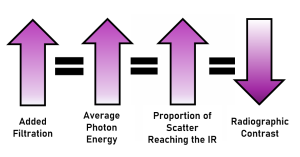
As the amount of filtration increases,
- The average photon energy in the beam, i.e. the beam quality, increases.
- As the average energy of the beam increases, the proportion of scattered radiation reaching the image receptor increases.
- Increased proportions of scatter on the image results in decreased contrast.
Filtration and IR Exposure
The filter’s main effect is on low energy photons, but photons of all energies can be absorbed by a filter. The reduction of photons of all energies from the beam will decrease IR exposure because the total quantity of radiation in the beam is decreased.
Figure 11-4: Impact of Filtration on IR Exposure
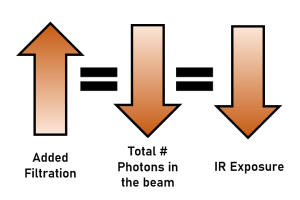
As the amount of filtration increases,
- The total number of photons in the beam decreases.
- Because there are fewer photons in the beam, fewer photons reach the IR, and IR exposure is decreased.
A minimum of 2.5 mm aluminum equivalent of diagnostic filtration is required for all radiographic units operating above 70 kVp of energy. This amount of filtration will decrease the beam intensity by about 1/2.
Filtration and Accuracy Properties
Because filtration does not change the geometric relationships of the tube, patient and image receptor, it does not impact spatial resolution or distortion.
Filtration and Patient Dose
Though filtration will decrease the beam intensity, its primary purpose is the removal of the long wavelength (low energy) photons that increase the exposure to the skin of the patient without substantially affecting the radiographic image. A filter is a material placed between the anode of the x-ray tube and the patient’s body. A filter absorbs low energy photons from the x-ray beam, and this decreases the patient’s radiation dose. Filtration also affects the amount of scattered radiation on the radiography and the amount of radiation reaching the image receptor. Filtration has an effect on both the quantity and quality of the x-ray beam and therefore affects both contrast and IR exposure. However, filtration’s primary purpose is not to affect contrast and IR exposure. The main purpose of filtration is to protect the patient’s body from excess radiation. Diagnostic filtration is estimated to reduce entrance skin exposures by about 50% compared to an unfiltered beam.
Figure 11- 5: Filtration and Patient Dose
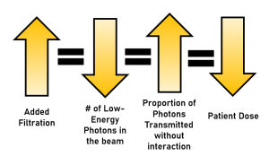
As the amount of filtration increases,
- The number of low-energy photons is decreased.
- The proportion of photons that pass through the patient without interacting increases.
- So, patient dose is decreased.
Rectification and Phase Generation
Another factor that affects the average energy of the x-ray beam is the type of rectification and generator used in the x-ray circuitry. Rectification is the process of changing alternating current into direct current. We want to rectify the electricity before sending it through the x-ray tube so the electrons flow from cathode to anode and not the other way around. Electrons flowing backwards would damage the filament and not result in the creation of x-rays. Alternating Current (AC) normally flows backwards and forwards over time. If we graph the number of electrons flowing through an AC circuit in a particular direction over time, we get a sine wave. See Figure 11-6.
Figure 11-6: Graph of AC Voltage Changes Over Time
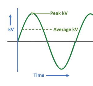
kVp fluctuates during the exposure. This produces an x-ray beam in which the photons have many different energies. The highest point in each cycle is the peak kilovoltage. The average voltage is approximately 1/3 of the kVp set on the control panel.
When we rectify a single line of electricity, or phase, we reroute the electrons flowing in the negative direction so they are flowing the correct way through the x-ray tube. When we graph the voltage of the rectified phase of electricity over time, we get pulsating direct current, as shown in Figure 11-7. In the simplest type of x-ray generator, a single phase generator, the kilovoltage will vary from zero to the kVp set on the control panel. When the voltage drops, the top energy of the x-rays that can be produced drops. When the energy of the x-rays drops, the penetrating power of our x-ray beam drops. When the penetrating power of the x-ray beam drops, patients get higher radiation doses because they absorb more of the beam.
Figure 11-7: Single Phase Full-Wave Rectification
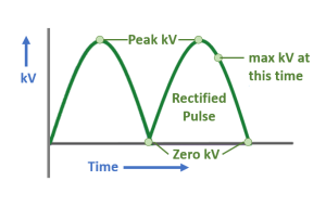
In full-wave rectification, the electricity traveling in the wrong direction is rerouted so that it travels the correct direction through the x-ray tube. When we look at this graph, the green line represents the highest possible voltage at that particular time. This means that the voltage varies from zero to the kVp we set on the control panel over the course of the x-ray exposure.
Modern x-ray systems use three lines of electricity, or three phases, to keep the voltage from dropping to zero during the exposure. Three-phase electricity basically divides the total amount of electricity provided to the x-ray tube into three chunks and provides that portion of the electricity to the x-ray circuitry at a different time than the other 2 phases. When three-phase power generation is used to power the x-ray tube, the graphs of the maximum voltages overlap and prevent the voltage from dropping to zero. See Figure 11-8.
Figure 11-8: Three-Phase Full-Wave Rectification
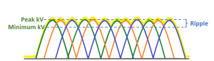
When using three-phase power generation, the voltages for each phase of electricity overlap. This prevents the kV from dropping to zero, and ensures that the energy levels of the x-rays produced stay high. The percentage of voltage variation over time is called ripple.
The fluctuation of the voltage when we have multiple overlapping pulses of electricity is called ripple. Ripple is how much the voltage drops or the percentage of voltage variation. For single phase electricity, the ripple is 100%, because the voltage drops all the way to zero. Three-phase, six-pulse waveforms have a 14% ripple, indicating that the voltage never drops below 86% of the kVp set on the control panel. Three-phase, twelve-pulse waveforms have a 4% ripple, indicating that the voltage never drops below 96% of the kVp set on the control panel. In addition to three-phase power generators, x-ray equipment is also available with a high-frequency generator. High-frequency generators have approximately 1200 cycles per second (as opposed to 360 cycles/second in three-phase units) and maintain a nearly constant voltage output with a ripple of less than 1%. High-frequency units are cheaper than 3-phase units, allow shorter exposure times and, because of the constant voltage output, have greater consistency in image quality. They are also capable of using standard 120 volt electrical outlets. Currently, most mammography, portable and CT machines use high-frequency power generators.
Key Takeaways
Decreasing the percentage of ripple through rectification, three-phase power generation or high frequency generators, increases the consistency of the kVp.
Increasing the consistency of the kVp increases the average energy of the beam because the highest energy levels are produced for more of the exposure.
- More pulses = Less ripple = Higher average electron energy = Higher average photon energy
- Fewer pulses = More ripple = Lower average electron energy = Lower average photon energy
- For Ripple: Biggest 1Φ 2 P > 3 Φ 6 P > 3 Φ 12 P > High Frequency Smallest
- For electron and photon energy: Lowest 1Φ 2 P < 3 Φ 6 P < 3 Φ 12 P < High Frequency Highest
Phase Generation and Beam Quality and Quantity
Phase generation and IR Exposure
There are 3 ways in which decreasing percentage of ripple with phase generation increases IR exposure:
- Increasing the total number of photons produced in the tube.
- Increasing the number of primary beam photons that pass through the patient without interacting.
- Increasing the proportion of scatter produced and the average energy of the scattered photons.
Increasing the total number of photons produced
As we have learned, phase generation with larger ripple reduces the average energy of the electrons crossing the x-ray tube. Likewise phase generation with smaller ripples increases the average energy of the electrons crossing the tube. The effect on IR exposure of changing phase generation types is the same as if we had increased the average electron energy by increasing the kVp. If the average energy of the electrons crossing tube is increased, the electrons bounce around more in the anode, and every bounce produces an additional x-ray. So, when we move from an x-ray machine with a single-phase generator to one with a three-phase, six-pulse generator, the incident electrons bounce around more because they have more energy. Each bounce produces an additional x-ray and the increase in interactions increases the total number of photons produced.
Increasing the average energy of the beam
Phase generation with lower ripple produces a beam with higher average energy. When the energy of the beam increases, more photons pass through the patient without interacting. This increases the number of photons reaching the image receptor.
Increasing the proportion of scatter
As the average energy of the beam increases, the proportion of Compton scatter interactions increases significantly. Since the photons interacting in the patient’s body are being scattered, rather than being completely absorbed, these photons also increase the total number of photons reaching the image receptor. Additionally, since the primary beam photons have higher energy, the scattered photons they produce also have higher energy. Higher energy scattered photons are more likely to escape the patient’s body and reach the image receptor.
Phase generation and Contrast
Image contrast is determined by the amount of scatter reaching the image receptor. Factors that increase the production of scatter decrease contrast. Factors that reduce the production of scatter or prevent it from reaching the image receptor increase contrast. Since decreasing the voltage ripple with rectification and phase generation increases average energy of the beam, the proportion of Compton scatter interactions increases significantly. Recall that scattered radiation reaches the image receptor in a way that puts a uniform layer of “gray ick” over the anatomical information we are attempting to visualize. As the amount of scatter reaching the image receptor increases, the layer of gray ick reduces the subject contrast differences between similar anatomical structures, reducing contrast.
Phase Generation and Spatial Resolution
Spatial resolution is determined by geometric factors and is not affected by the number of photons in the beam or the amount of scattered radiation reaching the image receptor. Because rectification and phase generation do not change the size of the focal spot, the SID or the OID, rectification and phase generation do not affect spatial resolution.
Phase Generation and Distortion
Distortion is determined by geometric factors and is not affected by the number of photons in the beam or the amount of scattered radiation reaching the image receptor. Because rectification and phase generation do not change the SID, the OID, or the relationships between the tube, body part and image receptor, rectification and phase generation do not affect distortion.
Phase Generation and Patient Dose
Summary
A filter absorbs low energy photons from the x-ray beam before the photons can enter the patient’s body, thus reducing the patient’s radiation dose. The decrease in the total number of photons in the beam decreases image receptor exposure. Filtration increases the average energy of the beam. This causes an increase in the proportion of scattered radiation reaching the IR, which reduces contrast. The total amount of filtration is the sum of the inherent and added filtration. Minimum total filtration levels are mandated by law, with most diagnostic radiography units requiring 2.5 mm aluminum equivalent of total filtration.