10 Grids and Beam Restriction
This section discusses the subject of scattered radiation control. Scattered radiation reduces radiographic contrast by placing a layer of fog or grayness over the image.
Learning Objectives
At the end of this chapter you should be able to:
- Compare the energy and direction of scattered radiation to primary radiation.
- Describe the effect of scattered radiation on IR exposure and contrast.
- Differentiate between the construction of a focused, parallel and crossed grid.
- Explain how a grid absorbs scattered radiation.
- Define grid ratio.
- List the most common grid ratios.
- Assess which grid ratio is the most efficient at absorbing scattered radiation.
- Define the term grid frequency.
- Describe how to avoid the five methods of producing grid cut-off.
- Describe the grid focusing distance and focal range.
- Differentiate between a grid and a Bucky.
- Explain how it is decided when a grid should be used and what type should be used.
- Calculate the new mAs to be used when changing from nongrid to grid, or when changing grid ratios.
Key principles of Grids
The amount of scattered radiation that hits the image receptor can be controlled by either prevention the production of scatter in the patient’s body, or by preventing the scatter from reaching the image receptor after it is produced in the patient’s body. One device that prevents the production of scatter in the patient’s body is the collimator. The collimator and several other devices and techniques will be discussed in the next chapter. The grid is the device that prevents scatter from reaching the image receptor and is the subject of this chapter. The Bucky, which is used to move the grid during the exposure, will also be described.
Key Takeaways
The amount of scatter radiation reaching the image receptor can be controlled by:
- Preventing the production of scatter in the patient’s body
- Collimation and other devices and techniques reduce the amount of scatter produced in the patient’s body
- Preventing the scatter produced in the patient’s body from reaching the image receptor
- Grids prevent scatter from reaching the IR
Scattered Radiation
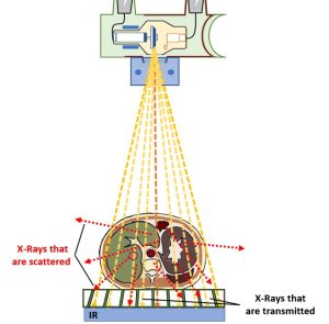
Primary radiation is produced in the x-ray tube and is aimed toward the patient’s body. When the photons in the beam enter the body they interact with the atoms in the patient’s body. Sometimes the photons are absorbed by the components of the body, and sometimes they pass right through the patient’s body and deposit energy from the radiation in the image receptor. The photons can also be scattered. See Figure 10-1.
Figure 10-1: Scattered Radiation
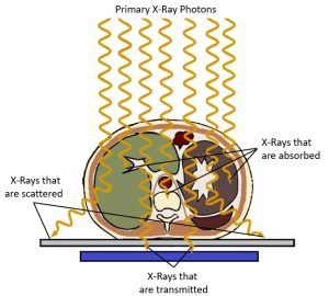
Primary radiation that interacts in the patient’s body and changes direction is called scattered radiation. Scattered radiation reaches the image receptor randomly and deposits energy that does not represent the anatomy. This extra radiation exposure decreases contrast and can hide the anatomy.
Scattered radiation is produced when a primary photon hits an atomic particle, usually in the patient’s body, and then the photon is deflected off the atomic particle. The primary photon is scattered. Scattering causes the primary photon to change its original direction and lose energy. The new direction could cause the scattered radiation to bounce back toward the x-ray tube, shoot out of the patient’s body in all directions, or hit the image receptor.
Key Takeaways
Scattered radiation that hits the image receptor affects the receptor by putting additional energy into it. This energy is extra information that does not represent the anatomy and is not good for the image. Scatter puts a layer of gray equally over the whole image, making the image appear to have low contrast. The differential absorption between adjacent structures are muted, and some structures are hidden in the image. Scatter produces an image with a very long scale of contrast and reduces the quality of the whole image.
Key Takeaways
Grids and Contrast
In 1913, Dr. Gustave Bucky invented a device called the grid. The grid is placed between the patient and the image receptor. The grid absorbs scattered radiation and prevents the scatter from reaching and affecting the image receptor. When a grid is used, radiographic contrast increases. The grid is the primary factor used to decrease scatter and increase contrast.
Key Takeaways
- Grids are placed between the patient and the image receptor.
- Using a grid increases radiographic contrast.
Grid Construction
Grids are made to match the sizes of the image receptors being used. The grid is constructed of lead strips that are so thin that they are sometimes referred to as lead foil strips.
When the lead strips are assembled to make a grid, the are placed on edge next to one another. If the grid were assembled on top of a table, the strips would be placed side-by-side perpendicular to the table top.
Each strip is separated from the others by a space called an interspace. The material used in the interspace can be a type of carbon fiber, plastic, or aluminum. The interspace material must be radiolucent, which means it should not absorb the x-ray beam. The strips and interspaces are bound together and covered by aluminum or plastic to give the grid strength. See Figure 10-2.
Figure 10-2: Grid Construction
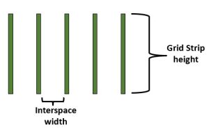
Grids are made of a series of lead strips separated by interspaces made of a radiolucent material such as aluminum, plastic or carbon fiber. These measurements are used to calculate the grid ratio. The grid ratio tells us how effective the grid will be at removing scatter.
If a grid is made to match the size of a 14 x 17 inch image receptor, the surface of the grid that measures 14 x 17 is called the face of the grid. A line, called the center line, is usually drawn on the face of the grid, which lets the radiographer know the direction of the grid lines, since they are hidden by the grid’s cover. The direction of the grid lines is very important to know when using the grid so the problem of grid cut-off can be avoided. This problem will be discussed later in this chapter.
If the cover were not on the grid, the radiographer could look that the thin edge or side of the grid and see the vertically placed grid strips.
Grid Patterns
Figure 10-3: Grid Patterns
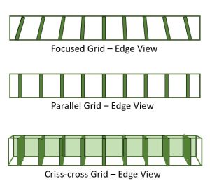
Grid patterns viewed from the edge and face.
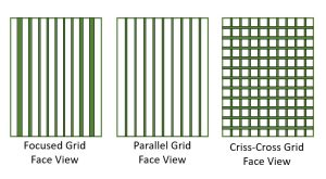
- Focused grids have their grid strips aligned to correspond to the divergence of the beam at a particular SID. When viewed from the face, the grid strips appear wider at the outer edges of a focused grid because those grid strips are angled more than the strips near the center of the grid.
- Parallel grids have their grid strips aligned perpendicular to the face of the grid, so they appear very similar in both the edge view and the face view.
- Criss-Cross grids form a cross-hatch pattern when viewed from the face. When viewed from the edge, criss-cross grids look pretty much like parallel grids except you can’t see down the entire length of the grid strips.
Focused Grid
The most common type of grid pattern in use is the focused grid. When the grid strips are placed on edge during the construction of a focused grid, they are not all placed parallel to each other. The strips in the very center of the grid are parallel to each other, but the strips at the sides of the grid are angled. The angle increases as the strips get closer to the sides of the grid.
It’s a pretty smart design, because the grid strips are aligned to match the way the primary photons emerge from the x-ray tube. The x-ray beam is pyramid-shaped, and the primary photons near the central ray are not at much of an angle when they reach the image receptor. The photons at the edge of the image receptor are at more of an angle. See Figure 10-4.
Figure 10-4: Function of the Grid
Because the lead strips in a focused grid are angled to match the divergence of the beam, most of the primary beam x-rays that are transmitted through the patient pass through the grid without being absorbed. Since the scattered photons are traveling at different angles from the primary photons, most of the scattered photons run into a lead strip and are absorbed before they can reach the image receptor.
When the x-ray beam hits the grid, the grid is supposed to let the primary photons through it and absorb the scattered photons. If the primary photons and grid strips are aligned, the primary photons will pass through the grid. Since scattered radiation travels in a changed direction from the primary radiation, it is more probable that the scattered photons will be absorbed by the grid strips. The scattered photons will hit the grid from a different angle than the primary photons and may run right into the lead strips of the grid. The lead strips will then absorb the scattered photons. When a primary photon bounces off a part of the patient’s body, it loses energy as it is scattered. Since the scattered photons have lost energy, it becomes easier for the lead strips to absorb the scatter.
Key Takeaways
Parallel Grid
A parallel grid is another design or pattern of grid. This type of a grid is constructed the same way as a focused grid, but the grid strips are not placed at an angle. If the grid were assembled on a tabletop, all the grid strips would be place perpendicular to the tabletop and they would all be parallel to each other.
When looking at this type of grid from either the face or the edge of the grid, the strips are parallel to each other. This pattern does not match the way the x-ray beam emerges from the tube as well as the focused grid does.
Crossed Grid
The crossed grid is also called a criss-cross grid or a cross-hatch grid. It is a combination of two parallel grids. One parallel grid is placed on top of the other, but one of the grids is turned 90-degrees so that the lines of the two grids cross each other. The crossed grid is the pattern that will absorbed the most scattered radiation. It is not used often, though, because the x-ray tube cannot be angled at all when using it.
Grid Ratio
The grid ratio is an important feature of the grid. The grid ratio is defined as the relationship between the height of the lead strips and the distance between the strips. Grid ratios vary from 5:1 to 16:1. The most common grid ratios are 5:1, 6:1, 8:1, 12:1, 16:1.
Key Takeaways
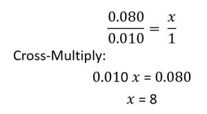
The grid ratio always ends with the number 1, so no matter what the actual measurements are of the height of the strips and interspace distance, the grid ratio must be converted to a certain number to 1. If the grid strips are 0.080 inch high, and the interspaces are 0.010 inch wide, the grid ratio is 8:1. The grid ratio is determined by setting up a proportion:
The actual measurements of the height of the grid strips and the interspace distance are unimportant after the measurements have been converted to a grid ratio. The grid ratio is the way the radiographer determines how much scattered radiation the grid will absorb or “clean up.” Most grids have a label that indicates the grid pattern and ratio.
A high-ratio grid (16:1) will absorb more scattered radiation than a low-ratio grid (5:1). A grid absorbs scattered photons that hit the grid strips. The grid strips extend up higher from the surface of a grid with a higher ratio, so the strips will be able to capture the scattered rays sooner and thereby absorb more of them. See Figure 10-5. Low ratio grids allow greater angles of scatter to pass through, while higher ratio grids allow less angulation.
Figure 10-5: Comparing Grid Ratios
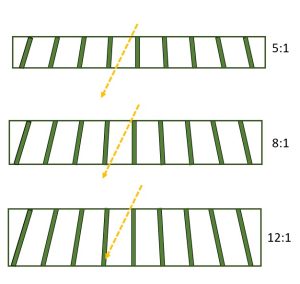
A scattered photon enters each of these grids at the same angle. It is absorbed by the higher ratio grid.
Key Takeaways
Grid Frequency
The grid frequency is defined as the number of grid lines per inch or centimeter. Grids with higher frequencies have thinner grid strips, so the resulting grid lines are less noticeable on the image. If the thickness of the grid strips remains constant, increasing the grid frequency reduces the interspace thickness and increases the grid ratio. The usual range is from 60 to 110 lines per inch (25 to 45 lines/cm). A grid with more grid lines per inch is more efficient at absorbing scattered radiation because it has more lead in it.
Key Takeaways
The grid frequency is defined as the number of grid lines per inch or centimeter.
- When strip thickness is constant, increasing the grid frequency reduces the interspace thickness and increases the grid ratio.
- Higher grid frequencies require greater increases in mAs to maintain receptor exposure.
Grid Cut-Off
A grid is designed to absorb the scattered radiation and allow the primary radiation to pass through it. However, if the grid is used incorrectly, the grid strips can absorb some of the primary radiation. this is called grid cut-off. Grid cut-off usually results in a radiograph that is unacceptable.
Key Takeaways
A radiograph with grid cut-off will have areas that appear lighter or brighter than they should. Sometimes the image of the grid lines can be seen in these lighter areas. Grid cut-off is usually seen on the edges of the radiographs.
Because the focused grid is the most common grid pattern, it is important to learn how to use it correctly and avoid grid cut-off. Grid cut-off with a focused grid can occur in five general ways:
- The wrong source-image distance is used.
- The x-ray tube is angled against the grid lines.
- The grid is angled in relation to the x-ray beam.
- The x-ray tube is not centered so that the central ray is over the center of the grid.
- The grid is used upside down.
Source-Image Distance (SID)
The SID used with a focused grid must fall within a certain range or the radiograph will display grid cut-off. The acceptable range is determined by the grid focusing distance. The grid focusing distance is an imaginary point in space above the face of a focused grid. If it were possible to extend the height of the focused grid strips, they would converge or meet at a point somewhere above the face of the grid, and that point would be called the grid focusing distance. See Figure 10-6.
Figure 10-6: Focusing Grid Distance
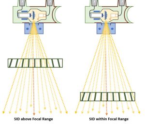
The grid strips of a focused grid are angled so that they are aligned with the pattern of the x-ray beam. So if the x-ray tube is placed at a source-image distance corresponding to the grid focusing distance, this would be the best place to allow the primary photons to get through the grid.
In actual use, there is a tolerance range that extends a little above and below the grid focusing distance. This range, called the focal range, is the acceptable range of source-image distances that can be used with a focused grid. If the x-ray tube is placed either above or below the focal range, grid cut-off can occur.
Key Takeaways
Angle of the x-Ray tube
Angling the x-ray tube against the grid lines will produce a noticeable grid cut-off. The line drawn down the center of the grid face indicates the direction of the placement of the grid lines in the grid. The x-ray tube can be angled either way in the direction of this line with no problem. Angling the tube across the grid lines, perpendicular to the center line of the grid, will produce grid cut-off. See Figure 10-7.
Figure 10-7: Angling Across the Grid Lines
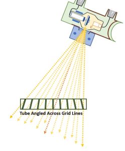
Grid cut-off is produced by angling the beam against the grid lines.
Key Takeaways
Angle of the grid
Grid cut-off also occurs if the x-ray tube is straight but the grid is at an angle. This causes the x-ray beam to be directed against the grid lines. This problem can occur in clinical practice during portable radiography when the patient is lying on an image receptor with a grid on top of it. The patient may be leaning more heavily on one side of the grid and image receptor than the other. This causes the grid and image receptor to be at an angle compared to the beam.
Key Takeaways
Centering of the X-ray Beam
Incorrect centering of the x-ray beam to the center line of the grid can cause grid cut-off on the radiograph. The x-ray tube should always be positioned so that the central ray is pointed at the center line on the grid. Grid cut-off is produced with the x-ray tube is moved across the grid lines, or perpendicular to the way the grid lines run in the grid.
Key Takeaways
Upside-down Grid
Using the grid upside down can occur accidentally. The center line on the face of the grid indicates the top side of the grid. The top side should be placed toward the x-ray beam with the image receptor underneath the grid.
If the grid is accidentally placed upside down, the center line will be pointing toward the image receptor instead of the x-ray tube. This mistake will produce a very noticeable grid cut-off. A brightter image will be displayed in the very center of the radiograph and the sides will appear almost blank.
Key Takeaways
The bucky
When a radiograph is taken with a grid, it is possible to see the lines of the grid on the radiograph. In 1920, Dr. Hollis Potter invented a device called the Bucky, which moves the grid during the exposure. This movement blurs the grid lines so they will not show up on the radiograph.
Key Takeaways
The most common type of Bucky device is a reciprocating Bucky. This moves the grid from side to side during the exposure. If the Bucky device fails to move the grid, or if it moves too slowly, the grid lines may appear on the radiograph.
A Bucky device is located directly under the x-ray table. A Bucky can also be installed in equipment used for upright radiography. The device consists of a focused grid and a motor to move the grid. The Bucky device also has a tray where the image receptor is placed. The tray does not have the grid on it. The grid is positioned above the tray and image receptor and usually cannot be seen.
All the precautions mentioned to avoid grid cut-off with a focused grid have to be adhered to when using the Bucky device in the x-ray table or upright equipment, because a focused grid is part of the equipment.
Grid Selection
How does a radiographer decide when to use a grid? And when a grid is necessary, what pattern and grid ratio should be used? In most departments there is a standard protocol for grid use. When the protocol is established, these factors should be considered:
- the size of the body part being examined
- the kVp used
- the amount of contrast required
- the possibility of grid cut-off
- the grid pattern
A general rule states that a grid should be used with the patient’s body part measures more than 10 cm (4 in). More scattered radiation is produced when the patient’s body part is large because there are more atoms for the x-ray photons to collide with.
Another general rule states that a grid should be used when the kVp has to be set above 60. More scattered radiation is produced with a high kVp. At techniques above 90 kVp, a grid ratio of at least 8:1 is usually required. If a high grid ratio is used, the grid will abosorb more scattered radiation. If it is necessary to produce a radiograph with high contrast, a high ratio grid should be used.
There is a greater chance of producing grid cut-off with a higher ration grid. During portable radiography, when problems may occur with alignment of the central ray and grid, it may be better to use a lower grid ratio.
A criss-cross grid will absorb the most scattered radiation, but the x-ray tube cannot be angled at all with this type of grid. The grid lines will absorb the primary radiation no matter which way the tube is angled.
Grids and IR Exposure
Because the grid is placed between the patient and the image receptor and absorbs photons, the exposure to the image receptor decreases when a grid is used. There are two reasons for this. A radiograph taken without a grid has more scattered radiation on it than one taken with a grid. Scattered radiation increases the exposure to the image receptor even though it is unwanted and doesn’t represent the anatomy. The absence of scattered radiation on an image produced with a grid reduces the exposure to the image receptor when compared to an image produced without a grid. Also, when a radiograph is taken with a grid, the lead in the grid will absorb some primary radiation, even when it is being used correctly. This causes less radiation to reach the image receptor and reduces IR exposure.
Technique Compensation with a Grid
The radiographer needs to increase the exposure factors whenever a grid is being used to maintain the correct IR exposure. Suppose a radiographer takes a radiograph that demonstrates good IR exposure without a grid using 5 mAs and 70 kVp. If the radiograph is taken again and a grid is used for the second exposure, the exposure factors need to be increased or the second radiograph will not have enough exposure to produce an optimum image. If the radiographer switches from using a grid to not using a grid, the exposure factors would need to be decreased. The amount of technique compensation, i.e. the amount of exposure increase or decrease, depends on what grid ratio was used for the original exposure compared to the second exposure.
The compensation used for the grid is just one of several technique compensations. We have already discussed technique compensations for changes in distance and changes in kVp. The first thing to do when calculating the technique compensation with a grid is to form a fraction with the grid ratio multipliers. These are listed in Figure 10-1 below.
Figure 10-1: Grid Ratios and Multipliers for Calculating Technique Compensation
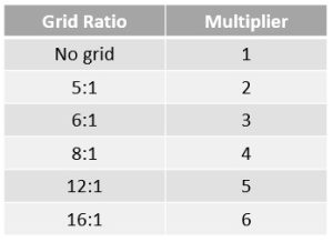
The number beside the grid ratio is the multiplier. The multipliers are used in the technique compensation formula to determine the new mAs that should be used. The technique compensation formula for
The multiplier of the grid ratio being changed to goes on the top of the fraction and becomes the numerator. The multiplier of the grid ratio being changed from goes on the bottom of the fraction and becomes the denominator. The number 5 is the multiplier for a 12:1 ratio grid, and 3 is the multiplier for a 6:1 ratio grid. So if the grid ratio is changed to a 12:1 ratio grid from a 6:1 ratio grid, the fraction would be 5/3. Once we have created the fraction with the grid ratio multipliers, we multiply the original mAs by the fraction. The answer is the new mAs to be used because of the grid change.
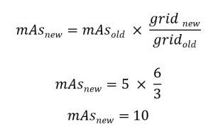
Example 1
The original radiograph was taken with a 6:1 grid ratio at 5 mAs and 80 kVp. The repeat radiograph is taken with a 16:1 ratio grid. What new mAs is required?
Example 2
The original radiograph was taken without a grid at 8 mAs and 70 kVp. The repeat radiograph is taken with a 12:1 ratio grid. What new mAs is required?
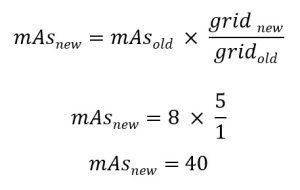
Some radiography references suggest increasing or decreasing kVp to compensate for grid use. Since kVp changes the amount of scattered radiation produced, this is not wise. If a grid is being used to decrease scattered radiation on the radiograph, and then the kVp is increased to compensated for the use of the grid, the increase in kVp will cause more scattered radiation to be produced. Therefore, the higher contrast achieved by using a grid would be canceled by the lower contrast caused by increasing the kVp. mAs should be the factor used to compensate for grid use because mAs does not change the amount of scatter radiation produced.
Key Takeaways
Grids, Spatial Resolution And Distortion
Because the grid does not change the size of the focal spot or the size of the pixels in the image matrix, it does not influence spatial resolution. Because grid use does not change the SID, OID or beam angle, it does not influence size or shape distortion.
Grids and Patient Dose
Any time we change the mAs used in the exposure, patient dose will change. When we increase mAs to compensate for using a grid, patient dose increases. When we decrease mAs to compensate for using a lower grid ratio or removing the grid entirely, patient dose decreases. A new feature recently introduced with digital imaging systems is a “digital grid.”
Digital Grids
More info coming soon….
Key principles of Grids
A grid is used to absorb scattered radiation and prevent it from reaching the image receptor. A grid consists of lead strips standing on edge separated by interspaces. The focused grid is the most common pattern.
Grid cut-off is the unwanted absorption of primary radiation by the grid. Grid cut-off can be avoided by using a source-image distance that is within the focal range, angling the tube only in the direction of the grid lines, avoiding an angle of the grid, centering the central ray to the center of the grid and using the grid right side up.
A Bucky device moves the grid so that the grid lines will not appear on the radiograph.
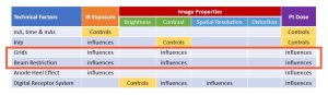
Overall, use of a grid will remove scatter from the remnant beam prior to it hitting the image receptor. By removing scatter, we increase contrast, because we are removing that layer of gray ick that coats the image when scatter is present. However, when photons are removed from the beam, IR exposure decreases, even when the photons removed were unwanted. In order to maintain the IR exposure when changing, adding or eliminating a grid, the mAs must be increased or decreased. Increasing mAs will increase patient dose. Decreasing mAs will decrease patient dose. See Figure 10-2 below.
Figure 10-2: Grids, IR exposure, Image Properties, and Pt. Dose
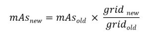
To calculate the new mAs, form a fraction by placing the multiplier of the new grid ratio in the numerator and the multiplier of the old grid ratio in the denominator. Then, multiply the old mAs by this fraction.
Key principles of Beam Restriction
We have seen that grids prevent scattered radiation from reaching the image receptor. But we can also control scatter by using beam restriction. Beam restriction prevents the production of too much scattered radiation inside the patient’s body. The grid and collimation are the primary methods used to control scattered radiation.
Scattered radiation is produced in the patient’s body when primary photons from the x-ray tube hit matter in the patient. The photons then travel off in a changed direction. They also have less energy. Thus, it is in the patient’s body where the majority of scattered radiation is produced.
The amount of scatter produced depends on how much matter in the body is hit with radiation. If a large are of radiation covers the patient’s body, the radiation will hit more matter and produce more scattered radiation because there are more atoms for the photons to collide with. If the size of the x-ray beam when it hits the patient’s body is small, less scattered radiation will be produced. Also if the patient is large, there is more matter present in the area of radiation, and more scattered radiation will be produced that if the patient is small. The saying “more matter = more scatter” will help you remember how this works.
Key Takeaways
The x-ray beam as it emerges from the x-ray tube takes the shape of a pyramid. the photons diverge, or move away from each other, as they leave the anode of the x-ray tube. Therefore as the beam travels away from the tube, it gets larger in size. If it were unrestricted when it reached the patient’s body, it would be quite large and cover a large area of the body. This would not only produce a lot of scattered radiation but also radiate more of the patient’s body than necessary and increase the radiation dose to the patient.
Key Takeaways
A beam that is larger than the image receptor being used will not record any more information on the image receptor than a beam that is adjusted to match the size of the image receptor. There is never an advantage to having the x-ray beam larger than the size of the image receptor. There are two advantages to using a small beam size: less scattered radiation production and a lower radiation dose to the patient.
There are several devices used to restrict the x-ray beam. Two older devices are the aperture diaphragm and the cone. The collimator is the most effective and used almost exclusively now, so this is the only device this book will discuss.
The collimator
The collimator is a box-like device attached at the edge of the x-ray tube, right under the window of the x-ray tube. The x-ray tube sits right above the collimator.
The collimator box has several lead shutters in it. The lead shutters absorb the edges of the beam as it emerges from the anode so that the beam will be smaller when it hits the patient. The collimators also shape the beam so that it will be rectangular to match the rectangular shape of the image receptor being used.
The radiographer can adjust the shutters inside the collimator with dials that are on the outside of the collimator. The shutters move in and out, making the x-ray field size smaller or larger.
X-ray equipment once used a device called automatic collimation or positive beam limitation. This device automatically adjusted to the size of the image receptor being used. A sensor, located in the Bucky tray, detects the size of the image receptor. This causes a motor to move the collimator shutters to adjust the beam to match the size of the image receptor in the Bucky tray. Automatic collimation is no longer a federal requirement on modern x-ray equipment because we no longer change the image receptor size according to the exam being performed. This law was intended to prevent radiographers from using a field size that was larger than the image receptor. It worked well to reduce patient dose when the radiographer had a range of image receptor sizes to choose from and selected the smallest image receptor that the body part would fit on. However, advancements in digital image receptors have resulted in a single large image receptor being used for all exams. This means that the positive beam limitation will only collimate to 14 x 17 inches or 17 x 17 inches regardless of the size of the part. The radiographer is now responsible for collimating closely to the part being examined and we are seeing an increase in field sizes used for imaging all parts.
Further, positive beam limitation only works when the Bucky tray is being used. There are many times in clinical situations when the Bucky tray is not used. sometimes the radiographer places the image receptor on the tabletop or directly under the patient’s body when the patient cannot be moved from a stretcher or wheelchair. The Bucky is also not used during portable radiography. During these instances it is the radiographer’s responsibility to adjust the collimation field size to limit scatter production and limit the patient’s radiation dose.
Modern collimators are always equipped with a light that indicates the size of the x-ray beam at the patient’s body. The collimator light is produced from a light bulb in the collimator box. The light bulb shines on a mirror that is placed in the collimator at an angle. The mirror reflects the light from the light bulb onto the patient’s body. It is important that this light beam be adjusted correctly, otherwise the light on the patient’s body might not coincide with where the x-ray beam is actually being directed.
The collimator usually includes two centering guides. One guide placed in the collimator casts its shadow in the field light and indicates the exact center of the beam. The shadow usually shows up as a circle or “X” shadow. The other guide is a line of light that extends out the side of the collimation field. This helps the radiographer line up the centere of the x-ray beam with the center of the image receptor. Some x-ray equipment uses laser lights to show the center and/or edges of the collimation field.
Beam Restriction and IR Exposure
The IR exposure is affected by both the area of radiation directed at the patient’s body and the amount of scattered radiation produced within the patient’s body. If the area of radiation at the patient’s body increases, more scattered radiation is produced. This increases IR exposure. The mAs needs to be changed to compensated for the exposure changes when the area of radiation or collimation field size is changed.
Key Takeaways
Exposure Compensation
If the collimation field size is changed from a size that will cover a 14 x 17 inch image area to a size that will cover a 10 x 12 inch image area, the mAs should be increased by about 25%. If the change is from 14 x 17 inches to 8 x 10 inches, the mAs should be increased by about 40%. A change from a small area of radiation to a larger area of radiation will require a corresponding decrease in mAs.
Figure 10-3: Multipliers for Changes in Collimation Field Size
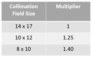
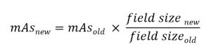
Figure 10-3 shows the multipliers for three sizes of collimation. Form a fraction by placing the multiplier for the new collimation field size in the numerator and the multiplier for the old collimation field size in the denomenator. Then multiply the original mAs by this fraction. The answer is the new mAs to be used because of the collimation change.
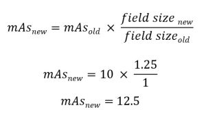
Example 1
A KUB radiograph is taken with a 14 x 17 inch field size using 10 mAs and 70 kVp. The radiologist requests a “coned down”(i.e. smaller field size) image of the left upper quadrant using a 10 x 12 inch field sized to increase radiographic contrast because of a suspected kidney stone in the left kidney. What new mAs is required?
Example 2
A preliminary image of the gall bladder is taken over the right upper quadrant with an 8 x 10 inch field size using 20 mAs and 70 kVp. The radiologist requests a KUB on a 14 x 17 inch receptor because she thinks the patient might have an early bowel obstruction and she needs to see the whole abdomen. What new mAs is required?
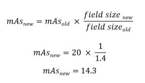
When changing from a 10 x 12 inch field size to an 8 x 10 inch field size, the fraction is 1.40/1.25. When changing from an 8 x 10 inch field size to a 10 x 12 inch field size, the fraction is 1.25/1.40.
Beam Restriction and Contrast
Scattered radiation affects contrast as well as IR exposure. If the area of radiation at the patient’s body increases, more scattered radiation is produced. This decreases radiographic contrast.
Key Takeaways
Beam Restriction and Accuracy Properties
The lead shutters absorb the edges of the beam as it emerges from the anode so that the beam will be smaller when it hits the patient. Because the collimator shutters eliminate photons from the edges of the beam, the remaining photons in the beam are more vertical and diverge less than the photons that were eliminated.