8 Radiographic Distances
The four radiographic qualities introduced in Ch. 4 are brightness, contrast, spatial resolution and distortion. We also need to emphasize image receptor exposure, as it plays a big role in overall image quality. As we have seen in Ch. 5 & 6, image receptor exposure and contrast are controlled by the quality and quantity of the photons in the beam and these are controlled by mAs and kVp. The other two radiographic qualities – spatial resolution and distortion are controlled by the geometric properties of image production. In Ch. 7, we learned about one geometric factor, focal spot size, and discovered that the only thing focal spot size affects is spatial resolution.
In this chapter you are going to learn about another of the primary exposure factors: radiographic distances and their relationships to the quality of the IR exposure, patient dose and the four image properties. You will learn about the relationship of radiographic distances to spatial resolution and distortion and how they impact image quality. You will also learn about the inverse square law and how it impacts IR exposure.
Learning Objectives
At the end of this chapter, you should be able to:
- Describe the changes in radiation intensity at the image receptor as the distance between the x-ray tube and image receptor is increased or decreased.
- State the inverse square law and its formula.
- Use the inverse square law formula to calculate the new radiation intensity when SID is increased or decreased.
- Use the inverse square law rule of thumb to calculate the new radiation intensity when the SID is doubled or cut in half.
- Explain what happens to IR exposure as the SID is increased or decreased.
- State the Exposure Maintenance Formula.
- Use the exposure maintenance formula to calculate the new mAs when the SID is increased or decreased.
- Use the exposure maintenance formula rule of thumb to calculate the new mAs that will maintain IR exposure when the SID is doubled or cut in half.
- Estimate the new mAs when the SID is increased or decreased.
- Explain how the Air-Gap technique is used to control scatter.
- Define the terms source-image distance, object-image distance, and source-object distance.
- Define size distortion.
- Explain how the object-image distance is used to control magnification.
- Explain how the source-image distance is used to control magnification.
- Describe the clinical applications of the most common source-image distances.
- Calculate the image size, object size, magnification factor and percent of magnification.
Radiographic Distances – A Quick Refresher
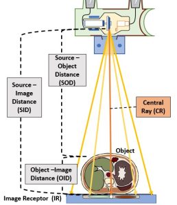
You will recall from Ch. 2 that there are three radiographic distances that the radiographer must be aware of and use good judgement in selecting. These distances include the Source-Image Distance (SID), which is the distance from the anode in the x-ray tube to the image receptor, the Object-Image Distance (OID), which is the distance from the patient, or an anatomical structure within the patient, to the image receptor, and the Source-Object Distance (SOD), which is the distance between the x-ray tube and the patient or a particular anatomical structure. We have also learned that these distances are mathematically related by the formula: SID = SOD + OID See Figure 8-1.
Figure 8-1: Radiographic Distances
Distance and the Radiographic Properties
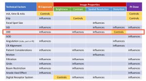
The four radiographic qualities of brightness, contrast, spatial resolution and distortion were described in Ch. 4. In Figure 8-2, all the factors affecting these properties as well as IR exposure and patient dose are listed in a chart. Notice that OID and SID are listed as factors that affect distortion.
Figure 8-2: Radiographic Distances, IR Exposure, Image Properties & Pt. Dose
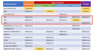
Look at the factors that affect recorded detail. SID and OID are listed as affecting spatial resolution. As the SID is increased by moving the x-ray tube away from the image receptor, the recorded detail is increased; and as the OID is increased by moving the object away from the image receptor, the recorded detail is decreased.
Source-image distance (SID) is listed as a factor that affects IR exposure. Whenever the SID is increased or decreased from the standard, the amount of radiation used for that radiograph needs to be adjusted. This adjustment is calculated with the density maintenance formula.
Object-image distance (OID) is listed as a factor that affects both IR exposure and contrast. This effect only occurs in the air-gap technique.
IR Exposure
The radiation intensity, or strength (in numbers) of the x-ray beam when it reaches the image receptor is a major factor in radiography. The intensity of the beam determines the strength of the electronic signal transmitted by the image receptor. The radiation exposure is controlled by milliammeter-seconds (mAs), which was discussed in Ch. 5, and is influenced by kilovoltage (kVp), which was discussed in Ch. 6.
SID and IR Exposure
The intensity of the beam at the image receptor is also influenced by the distance between the x-ray tube and the image receptor, which is the source-image distance (SID). This distance helps determine the strength of the electronic signal transmitted from the image receptor to the computer. The effect of the distance between the x-ray tube and the image receptor exposure is the focus of this section.
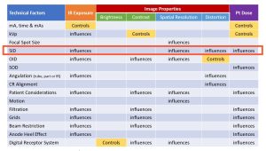
Figure 8-3: SID’s Impact on IR Exposure, Image Properties and Pt. Dose
The inverse square law, which enables radiographers to calculate the intensity of the beam at the image receptor when the distance between the x-ray tube and the image receptor changes will be presented first. After learning how distance changes the intensity of the beam, you must learn how to change the exposure factors to produce a radiograph with the proper exposure when the SID changes. This is done using the Exposure Maintenance Formula, or the Direct Square Law. This formula is used often in nonstandard clinical situations like portable x-ray, surgery, trauma, or emergency cases, so the concepts and calculations are important.
The Inverse Square Law
When you were a child, did you ever play under the water sprinkler on a hot day in the summer? Think about the type of sprinkler that remains stationary and sprays water from its center into a circular area. If you stand far away from it, you won’t get wet, but as you mover closer and closer you get wetter and wetter. See Figure 8-4.
Figure 8-4: X-Ray Intensity is Like Water from a Sprinkler

X-Ray photons, like water droplets from a sprinkler, get further apart as you move further away from the source.
The x-ray beam acts similarly to the water sprinkler. If you mover closer to the source of an x-ray beam or if the source of the x-ray beam is moved closer to you, the radiation becomes more intense (remember intensity is the number of photons in the beam) at your body. And if the source of the x-ray beam is moved farther away, the radiation becomes less intense at your body. In this instance, the amount of radiation coming from the x-ray tube dose not change, but the distance between you and the x-ray tube changes and that causes the amount of radiation reaching you to be more or less intense.
Now thing about pulling your car into a parking spot that is perpendicular to a building. At night, the light from your headlights on the building gets smaller as the car gets closer to the building. As the area of light gets smaller, the light on the building appears brighter.
The x-ray beam acts similarly to the headlights. As it is moved closer to an image receptor the beam covers a smaller area on the image receptor. As the x-ray tube is moved closer to the image receptor, the same amount or quantity of radiation used at the farther distance is now confined to a smaller area, and the radiation is more intense at the closer distance. As the x-ray tube is moved farther away from the image receptor the beam covers a larger area. The same amount or quantity of radiation used at the closer distance is now spread out and covers a larger area and the radiation is less intense at the farther distance. so both the size of the radiation area and the intensity of the radiation change as the distance between the x-ray tube and image receptor changes. This happens because the x-ray photons are emitted isotropically and diverge from their point of origin. See Figure 8-5. As the SID increases, the x-ray photons get further and further apart and the total number of photons per unit area decreases.
Figure 8-5: Diverging X-Ray Beam
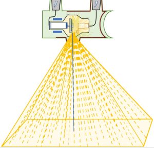
The photons diverge from the central ray, so the longer the SID is, the more spread out the photons become.
The intensity of radiation coming from the x-ray tube is measured in a unit called coulombs per kilogram, which is the amount of radiation required to create a charge of 1 coulomb in 1 kilogram of matter. Because coulombs per kilogram is a pretty large unit, when discussing the intensity of radiation in diagnostic imaging, we more frequently discuss exposure in terms of air kerma. Air Kerma is a unit measuring the kinetic energy released per unit mass of air, and is expressed in grays or milligrays. Air kerma can be thought of as the number of individual photons per unit area. It is used to estimate the peak skin dose to the patient, but doesn’t take into consideration the total area of the patient that is exposed.
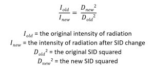
The distance between the x-ray tube and the image receptor is the source-image distance (SID). There is an inverse relationship between the SID and the radiation exposure at the image receptor (IR exposure). If the SID increases, the IR exposure decreases. And if the SID decreases, the IR exposure increases. The new IR exposure after any SID change can be calculated with the inverse square law formula. The inverse square law states that the intensity of radiation is inversely proportional to the square of the distance from the source of radiation.
Calculating the New Intensity
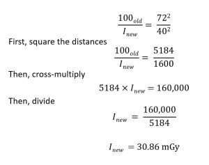
Usually the unknown factor is the new intensity. For example, what if the original amount of radiation intensity at the image receptor is 100mGy when the x-ray tube is at a 40-inch distance from the image receptor. If the x-ray tube had to be moved to a 72-inch distance from the image receptor, the amount of radiation intensity at the image receptor changes. The radiation intensity at the image receptor would be less if the x-ray tube is moved farther away. The same amount of radiation used at the original distance would be spread over a larger area becoming less intense. To calculate the new intensity:
Activity – Inverse Square Law
Rule of Thumb for Calculating Radiation Intensity
The change in radiation intensity after a change in SID is more than what might be expected. Students often make the mistake of thinking that if the SID is doubled, the radiation exposure is cut in half. When the SID is doubled, the area of radiation at the image receptor grows by 4 times because both the length and the width of the radiation are doubled. This spreads the radiation over an area which is four times larger than the original areal and this reduces the radiation intensity. When the SID is doubled, the radiation area increases by four times, but the radiation intensity decreases by four times. See Figure 8-6.
Figure 8-6: Inverse Square Diagram
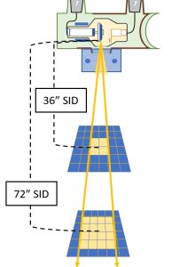
- The beam covers 4 squares at 36″ SID. The beam is more intense.
- The beam covers 16 squares at 72″ SID. This is 4 times the area covered at 36″ SID. The beam is less intense.
The radiation area is smaller and the radiation is more intense at a 36-inch SID. If the SID is doubled to 72 inches, the area of radiation is 4 times larger, but the radiation intensity is 4 times less than it was at the 36-inch SID.
The following is a rule of thumb that is helpful to remember.
Key Takeaways
- If the SID is doubled, the IR exposure becomes four times less.
- If the SID is cut in half, the IR exposure becomes 4 times greater.
If the radiation exposure at a 36-inch SID is 50 mGy, the radiation intensity at a 72-inch SID would be four times less, or 12.5 mGy. If the radiation intensity at an 80-inch SID is 70 mGy, the radiation exposure at a 40-inch SID would be 280 mGy.
Activity – Inverse Square Law Using the Rule of Thumb
Measuring Radiation Exposure
The amount of radiation exposure can be measured with a device called an ionization chamber. When using an ionization chamber, the arrangement for an ordinary x-ray exposure is used, except the ionization chamber is placed at the location where the image receptor would normally be placed. Then an exposure is made by exposing the ionization chamber to radiation. The ionization chamber measures the number of ionizations that occur inside the gas that fills it. The reading of the number of ionizations corresponds to the amount of radiation that reaches it.
The Exposure Maintenance Formula
There is another formula, derived from the concept of the inverse square law, with is very useful to the radiographer in clinical practice. This formula, called the exposure maintenance formula, or the direct square law, allows the radiographer to calculate the new exposure factors to be used when the distance between the x-ray tube and the image receptor changes.
The IR exposure determines the signal strength sent to the computer for processing. If two radiographs are taken with the same amount of radiation, but with different source-image distances, the intensity of radiation at the IR is different for each exposure.
If the IR exposure was satisfactory before the distance changed, it won’t be acceptable at the new distance because the radiation intensity has changed. When the SID changes, the intensity also changes. The mAs needs to be increased or decreased to compensate for the distance change.
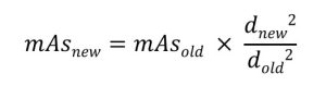
If the source-image distance decreases, the IR exposure increases, and so the mAs needs to be decreased to maintain the same IR exposure as before the distance change. Conversely, if the SID increases, teh IR exposure decreases and the mAs needs to be increased to maintain the IR exposure. The amount of increase or decrease of the mAs can be calculated with the exposure maintenance formula. The exposure maintenance formula states that the new mAs equals the old mAs multiplied by the new distance squared and divided by the old distance squared.
Calculating the New mAs with the Exposure Maintenance Formula
Assume that 1.25 mAs was used to produce a good radiograph at an original 40-inch SID. Then the SID was changed to 72 inches for a repeat radiograph. The radiographer needs to know what mAs to use at the new 72-inch SID to produce another good radiograph.
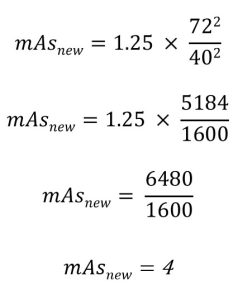
In this example the mAs must be increased from 1.25 to 4 because the SID was increased, which decreased the IR exposure. The two radiographs, the one with the 40-inch SID and 1.25 mAs, and the one taken with a 72-inch SID and 4.0 mAs should have the same receptor exposure.
Activity – Exposure Maintenance Formula
The exposure maintenance formula can also be used to calculate the new mA or exposure time. Instead of inserting mAs into the formula, either the mA or exposure time could be inserted and a new mA or exposure time can be calculated.
It isn’t too useful in clinical situations to calculate the new mA station because the mA station should be standard for the exam being performed. Usually a high mA should be used. This allows the use of a short exposure time, and short exposure times limit motion on the radiograph. So if a radiographer is already using a high mA station, that should not be changed.
The new time can be calculated when the SID changes instead of the new mAs. Then the radiographer would know what new time to use after one calculation rather than having to calculate the new mAs first and then the new time. In the example used to calculate the new mAs, assume that the original 1.25 mAs was achieved using 50 mA and 0.025 sec.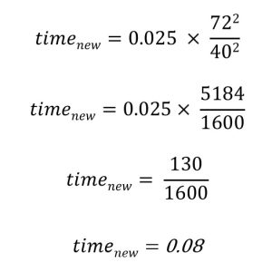
The new exposure time of 0.08 multiplied by 50 mA equals 4.0 mAs, which is the same mAs calculated in the original problem.
Activity – Exposure Maintenance with Time
Rule of Thumb for Calculating Exposure Factors
A rule of thumb can be used to calculate the new mAs when the SID is doubled or cut in half. The rule of thumb makes the calculations easier.
Key Takeaways
Rule of Thumb for Calculating Exposure Factors
- If the SID is doubled, the mAs needs to be increased by 4 times.
- If the SID is cut in half, the mAs needs to be decreased by 4 times.
If 1 mAs is used at a 36-inch SID, a mAs of 4.0 could be used at a 72-inch SID. The two radiographs would display the same IR exposure. If an exposure time of 0.10 sec is used at an 80-inch SID, an exposure time of 0.025 sec could be used at a 40-inch SID. These two radiographs would also display the same IR exposure.
Clinical Use
In clinical practice, the most commonly used source-image distances are 40 inches and 72 inches. A change of the SID from 40 to 72 isn’t an exact double of the distance. So the rule of thumb is used in this instance as an estimate. Because digital imaging has a much wider exposure latitude than film did, we don’t have to be exact. Estimating with the rule of thumb and then tweaking the new mAs up or down a bit to reflect the actual distance changed will get you close enough.
To maintain IR exposure when the SID and thus the radiation intensity is changed, the exposure maintenance formula is used. This tells the radiographer the new mAs or new time to be used with the SID is changed. If the SID is increased, the mAs or time must be increased. If the SID is decreased, the mAs or time must be decreased.
The relationships between SID, radiation intensity and IR exposure are clinically important. The radiographer must be able to calculate the technique changes required, and should be able to estimate the required changes.
OID influence on IR exposure
Figure 8-8: OID’s Impact on IR Exposure, Image Properties and Patient Dose

Under standard positioning protocols where the area of interest is placed in contact with the image receptor, OID will not impact IR exposure. However, if a large OID is employed, an interesting phenomenon occurs. When the radiographer intentionally uses a long OID to reduce scatter reaching the image receptor, that radiographer is using Air-Gap Technique. By placing the body part farther away from the image receptor, some of the scattered radiation produced in the patient’s body will miss hitting the image receptor. This increases radiographic contrast and reduces the IR exposure. The amount of scattered radiation reduction achieved with the air-gap technique is about equivalent to the effect of using a 6:1 ratio grid.
Key Takeaways
An Air-Gap increases contrast, but decreases IR exposure.
A large object-image distance will produce a very noticeable increase in magnification. We will talk about this next. This is compensated for by increasing the source-image distance. In clinical practice, the air-gap technique is used most often for a lateral cervical spine radiograph. A 6-8 inch air-gap is usually used with a compensating 72-inch SID. The increase in SID will also require an increase in mAs using the exposure maintenance formula to maintain IR exposure.
Contrast
Changes to the source-image distance do not affect the quality of the photons in the beam or the amount of scatter radiation reaching the image receptor, so SID does not affect contrast.
Size Distortion
Size distortion, or magnification, is defined as the misrepresentation in the image of the true size of the object, particularly in comparison to other structures in the patient’s body. Size distortion, or magnification, occurs when the image of the object on the radiograph appears larger than the actual size of the object. When this occurs, the image is magnified. The job of the radiographer is to make the image appear as close to the true size of the actual object as possible. So magnification on the radiograph is ordinarily not a good thing.
Key Takeaways
Size distortion is the misrepresentation in the image of the true size of the object, particularly in comparison to other structures in the patient’s body.
The best relationship to produce the least magnification is to have the object as close to the image receptor as possible and to have the x-ray tube as far away from the image receptor as possible. In technical distance terms, it is best to have a short object-image distance (OID) and a long source-image distance (SID).
Key Takeaways
Divergent rays were discussed in Ch. 1. Divergent rays occur because x-rays are emitted isotropically from the target. The portion of the emitted x-rays that exits the tube at the window takes the shape of a cone. If the beam is directed straight at the patient, the photons in the center of the beam are perpendicular to the patient, but the photons at the edges of the beam reach the patient at an angle.
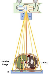
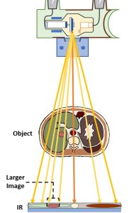
Because of those divergent rays, placing the object further away from the image receptor causes the object’s shadow or image on the receptor to be larger than it is when the object is placed very close to the image receptor. See Figure 8-9. Placing the x-ray tube closer to the object also causes the image of the object to be larger than it is when the tube is places farther away from the object.
Figure 8-9: Image Size Differs with Different OIDs
Object-Image Distance (OID) and Size Distortion
The object-image distance (OID) is the major factor controlling magnification. See Figure 8-10. The least magnification is produced when the object is placed close to the image receptor. Magnification increases as the object is moved further away from the image receptor, so an OID of 10 inches will produce more magnification than an OID of 5 inches.
Figure 8-10: OID’s Impact on IR Exposure, Image Properties and Pt. Dose
Proper positioning of the patient’s body will help avoid too much magnification. If the patient is lying on their abdomen face down (prone), then the patient’s spine is far away from the image receptor. The spine would be magnified on the radiograph and that wouldn’t be good if that is the structure the radiologist is interested in seeing. By turning the patient over to lie on their back (supine) the spine is moved closer to the image receptor and will appear much less magnified on the radiograph. It is important to learn the anatomy of the body and then learn how to position the patient’s body to put the structure of interest closest to the image receptor.
Key Takeaways
Always try to put the object or structure of interest close to the image receptor to avoid magnification.
Source-Image Distance (SID) and Size Distortion
A long source-image distance (SID) will produce the least magnification or size distortion. Size distortion increases as the x-ray tube is moved closer to the object, so an SID of 50 inches will produce more magnification than an SID of 60 inches.
Key Takeaways
Even though it sounds like it should be better to use a very long SID, the distance between the x-ray tube and film isn’t varied too much in clinical situations. The most commonly used SIDs are 72 inches or 40 inches. The 40 inch distance is usually used for radiographs exposed when the patient is lying on the x-ray table with the image receptor located in the bucky tray or on the table top, although newer machines are being designed for a standard 48 inch SID. The standard distance is used even though a moderate amount of magnification is produced. This amount of magnification is acceptable and expected. The longer distance of 72 inches is used when the image needs to be more precisely the size of the object. For example, the 72-inch distance is used for chest radiographs so that a minimal amount of magnification of the heart will appear on the radiograph.
In nonstandard situations the source-image distance (SID) can vary quite a bit, and this can make a noticeable difference in the size distortion on the radiograph.
The object-image distance and the source-image distance work together to produce the total amount of size distortion. In nonstandard clinical situations, the radiographer may be unable to get the object as close to the image receptor as possible. For instance, if a patient lying flat on the x-ray table were unable to straighten their knee and had to keep it bent, the knee would be up off the table and have an increased OID. The radiographer can compensate for this by increasing the SID above the standard 40 inches. This increase will help offset the magnification caused by the large OID.
Calculating Magnification
In some clinical situations it is important for the radiologist (or orthopedic surgeon) to know the amount of magnification produced on a radiograph. This is especially important during angiograms and mammography. The image size, object size, magnification factor and percent of magnification can all be calculated.
Object and Image Size
The ratio of the image size to the object size is proportional to the ratio of the SID to the SOD. When referring to “size” this is either the length of the image or object or the width of the image or object. We can write this comparison using a mathematical equation:
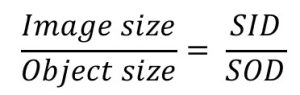
Since the proportion above, used to calculate the image or object size, uses the unit of SOD, it is first necessary to calculate the SOD (which is the SID minus the OID). Insert the known factors into the proportion, and then cross-multiply and divide to find the missing factor.
Let’s see an example:
If any of the other 3 factors in the proportion – object size, SID or OID – were the unknown factors, they could be calculated using the same formula.
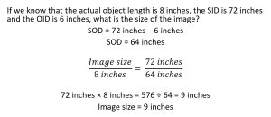
Magnification Factor
The magnification factor tells the radiographer how much larger the image will appear as compared to the object. If the magnification factor is 1.5, the image will be 1.5 times longer and 1.5 times wider than the object. A 1.5 times magnification of an object that is 4 inches long will cause the image to be 6 inches long (4 × 1.5 = 6).
There are two ways to calculate the magnification factor.
- Divide the source-image distance by the source-object distance.
- Divide the image size by the object size.
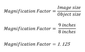
If the magnification factor is 1.125, the image would be 1.125 times longer and 1.125 times wider than the actual object. The image length or width can then be calculated by multiplying the object length or width by the magnification factor. 8 inches (the actual object length) times 1.125 is 9 inches (the image length).
A clinical example of this is the use of a radiographic reference ball when imaging patients prior to total joint replacement. See Figure 8-11.
Figure 8-11: Radiographic Reference Ball
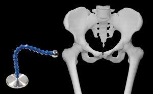
The metal ball at the end of the device is precisely measured and placed at the same level as the femoral head. This allows the image to be measured and the magnification factor calculated.
The head of the femur has a pretty large OID and is magnified on radiographic images. But the orthopedic surgeons must have very precise measurements so they order the correctly sized prosthetic for the surgery. The flexible neck of the device allows the radiographer to place the ball at the level of the greater trochanter, about the same distance from the image receptor as the head of the femur. Because the ball at the end of the device is precisely manufactured to be 25 mm in diameter, the image can be measured and the magnification factor calculated. Then the same magnification factor can be applied to the image of the femoral head and the actual size of the femoral head can be calculated. It is critical that the radiographer assures that the reference ball is placed at the correct level. If the ball is not at the same level as the femoral head, the magnification factor calculated will not be accurate.
The magnification factor tells the radiographer (and the physicians) how much longer and wider the image will be compared to the object’s actual length and width.
Percent of Magnification
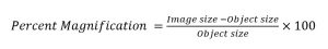
The percent of magnification is calculated by subtracting the object size (length or width) from the image size (length or width), dividing this answer by the object size (length or width), and then multiplying the result by 100.
To solve for percent magnification, both the image and object sizes must be known. In our last example, the image was 9 inches long and the object was 8 inches long. 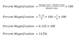
Activity – Calculation of Size Distortion
Spatial Resolution
We learned in Ch. 7 that a small focal spot will produce less unsharpness than a large focal spot. So, an image produced using a small focal spot will have better spatial resolution. But focal spot size isn’t the only thing that affects spatial resolution. SID and OID will both play a role in obtaining the best spatial resolution possible.
OID and Spatial Resolution
The object-image distance (OID) is the distance from the object being radiographed to the image receptor. The radiographer controls this distance when positioning the patient.
If the OID is increased, the area of unsharpness on the radiograph increases, and the image will display less spatial resolution. If the OID is decreased, the area of unsharpness decreases and the image will display better spatial resolution.
Key Takeaways
SID and Spatial Resolution
The source-image distance (SID) is the distance from the source of x-rays, which is the x-ray tube, to where the image is formed in the image receptor. Most of the time in clinical practice, standard source-image distances of 40- or 72-inchese are used. There are times, though, when these standard distances are varied.
If the SID is increased, the area of unsharpness on the radiograph decreases, and the spatial resolution improves. If the SID is decreased, the area of unsharpness increases and the spatial resolution decreases.
Key Takeaways
A large SID produces better spatial resolution.
Spatial Resolution and Distortion
Earlier in this chapter we discussed size distortion, which is also called magnification. There is a relationship between distortion and spatial resolution.
Size distortion and spatial resolution are both affected by the SID and the OID. If the OID increases, the image on the radiograph becomes more magnified. And increase in the OID also causes a decrease in recorded detail. If the SID increases, the image on the radiograph becomes less magnified. An increase in SID also causes and increase in recorded detail.
Key Takeaways
- As magnification increases, spatial resolution decreases.
- As magnification decreases, spatial resolution increases.
Calculation of Unsharpness
The geometric factors affecting recorded detail can be formed into an equation that is used to calculate the amount of unsharpness that will appear on the radiograph.
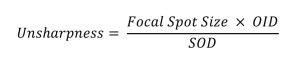
The following conditions will be used to calculate the amount of unsharpness when each geometric factor is changed:
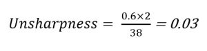
- Focal spot size = 0.6 mm
- OID = 2 inches
- SOD = 38 inches
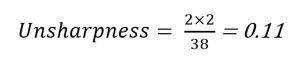
Focal Spot Size
If the focal spot size is increased, the amount of unsharpness increases. If the focal spot size changes from 0.6 to 2.0 mm, the amount of unsharpness changes to 0.11.
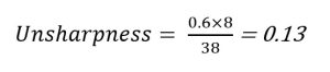
Object-Image Distance
If the object-image distance is increased, the amount of unsharpness increases. Referring back to the original factors, if the object-image distance changes from 2 inches to 8 inches, the amount of unsharpness changes to 0.13.
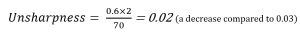
Source-Image Distance
If the source-image distance is increased, the amount of unsharpness decreases. Remember that the source-image distance is the sum of the object-image distance and the source-object distance. Thus if the OID stays the same and the SID is increased, the SOD is also increased. The SOD may have to be calculated before using it in the unsharpness formula. Referring back to the original factors, if the SOD changes from 38 inches to 70 inches, the amount of unsharpness changes to 0.02. In this instance, the SID is increased from 40 inches (38 + 2) to 72 inches (70 +2).
Summary
If the distance between the x-ray tube and image receptor, which is the SID, is changed, the IR exposure changes. If the SID is increased, the IR exposure decreases. And if the SID is decreased, the IR exposure increases. The new IR exposure after the distance changes can be calculated using the inverse square law.
To maintain IR exposure when the SID and thus the radiation intensity is changed, the exposure maintenance formula is used. This tells the radiographer the new mAS or new time to be used with the SID is changed. If the SID is increased, the mAs or time must be increased. If the SID is decreased, the mAs or time must be decreased.
The relationships between SID, radiation intensity and IR exposure are clinically important. The radiographer must be able to calculate the technique changes required, and should be able to estimate the required changes.
The air-gap technique can be used to decrease the amount of scattered radiation reaching the image receptor. This increases radiographic contrast and decreases IR exposure.
The distance from the x-ray tube to the image receptor is the source-image distance (SID). The distance from the object to the image receptor is the object-image distance (OID). The distance from the x-ray tube to the object is the source-object distance (SOD).
These distances control the amount of size distortion or magnification. Magnification causes the image to appear larger than the object. The least amount of magnification is achieved with a short OID and a long SID. The image size, object size, magnification factor and percent of magnification can all be calculated.
Spatial resolution is affected by five factors: the focal spot size, the object-image distance, the source-image distance, motion, and receptor properties.
The focal spot size, the object-image distance, and the source-image distance are the geometric factors that affect spatial resolution.
Spatial resolution improves and the radiograph will show less unsharpness with a small focal spot size, a short OID, and a long SID. Spatial resolution decreases and the radiograph will show more unsharpness with a large focal spot size, a long OID and a short SID.