1 Production and Properties of X-Rays
In this chapter you will learn about the construction and function of the x-ray tube. A satisfactory understanding of exposure and imaging terms requires at least a limited understanding of x-rays and their properties.
Learning Objectives
At the end of this chapter you should be able to:
- Name and describe the two parts of the cathode.
- Describe the appearance of the anode.
- Explain the purpose of the glass envelope and the tube housing.
- Draw a diagram of the x-ray tube and label the parts.
- Explain how the parts of the x-ray tube function to produce x-rays.
- Place the events involving the production of x-rays in chronological order.
- Differentiate between the terms anode, target and focal spot.
- Describe the interactions in the anode and the x-ray energies they produce.
- Explain these properties of x-rays: divergent rays, photon energy, visibility, speed, ability to produce scatter, effect on phosphors, effect on photodetectors, and the ability to cause biological damage.
Key Terms
X-rays are a form of invisible electromagnetic radiation and were discovered on November 8, 1895 by Wilhelm Conrad Roentgen. Electromagnetic radiation includes visible light as well as other “waves” like microwaves, radio waves and gamma rays. X-rays have similar properties to other types of electromagnetic radiation since they all travel at the same speed and obey many of the same laws. X-rays, however, are distinguished by their extremely short wavelength (about 1/10,000 the length of visible light waves). It is this short wavelength that enables x-rays to penetrate materials that normally absorb or reflect light.
A quick overview of x-Ray Generation
Basically, x-rays are produced when high speed electrons strike matter. This can occur inside or outside a vacuum. Because molecules of air can interfere with the travel of the electrons, creating x-rays in a vacuum is more efficient and effective. Since a vacuum is basically space without any matter in it, we need to contain the components for creating x-rays in something that can keep the air out. The device we use for keeping the air out and maintaining a vacuum for the x-rays to be created in is the x-ray tube.
The Vacuum
The modern x-ray tube consists of an evacuated (i.e. enclosing a vacuum) glass or metal bulb into which two electrodes – the cathode and the anode – are sealed. The glass bulbs are similar to an incandescent light bulb in which the filament glows instead of burning out because there is no air to support combustion (See Figure 1-1). In the original incandescent light bulbs, electrons from the electrode wires were connected by cotton filament. This caused the cotton to heat up enough to glow. The only reason the cotton didn’t burst into flames is because there is no air inside the bulb.
Figure 1-1: The Incandescent Light Bulb compared to a Coolidge X-Ray Tube


The Coolidge tube is one of the earliest designs of the x-ray tube. While the positive and negative electrodes in the light bulb both connect to the bottom of the bulb, the positive (left) and negative (right) electrodes of the x-ray tube are connected at opposite ends of the bulb.
The invention of the Coolidge type of x-ray tube made it possible to maintain a constant source of x-rays that could be easily duplicated at will because it was evacuated. The degree of vacuum of the Coolidge x-ray tube and the arrangement of the electrodes are such that no electricity can travel between the electrodes until the filament in the cathode is heated. The advent of the evacuated x-ray tube was a critical step in the development of diagnostic x-ray as a tool in modern medicine.
X-Ray Tube Construction
The inside of the x-ray tube consists of two main parts: the cathode and the anode. These two parts work together to produce x-rays. Electrons are released from the cathode, they zoom over to the anode, and when they collide with the anode x-rays are produced.
The Cathode
Figure 1-2: The Cathode Assembly of the X-Ray Tube
 |
 |
The cathode (Figure 1-2) is the negatively charged electrode. It consists of two filaments (usually) and a focusing cup.
The Filament
Figure 1-3: The Filament
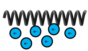
This shows a close up of the coiled filament. When the filament is heated, electrons escape from the metal of the filament and produce a cloud of electrons around the filament. (In this chapter, we will illustrate electrons that have escaped from the filament in blue. All other electrons will be shown in yellow.)
The filament’s role in x-ray production is to release electrons. The filament is a tiny wire made of tungsten and shaped into a coil or spiral. It looks a little bit like the spring inside a ball point pen. See Figure 1-3. Tungsten is the preferred filament material due to its ability to resist melting at high temperatures. Pure tungsten or a mixture of tungsten and thorium provide wire filaments with melting points of around 3400 degrees C or 6000 degrees F.When electrons flow through the filament, the filament heats up and some of the electrons are emitted and are then free to cross the x-ray tube. The number of electrons released is controlled by the number of electrons allowed to flow through the filament, which is described in electrical terms as the current or amperage.The higher the current, the higher temperature the filament reaches and the greater the electron emissions.
Key Takeaways
While an x-ray tube can function with one filament, there are usually two filaments. An x-ray tube with two filaments is called a dual-focus x-ray tube, because the selection of the filament controls the focal spot size for the exposure. The two filaments are positioned next to each other and are parallel to each other. The large filament is longer than the small filament.
The Focusing Cup
Figure 1-4: The Focusing Cup
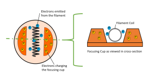
The orange structures in the diagram above are the focusing cup. The negative charge on the focusing cup repels the electrons released from the filament making a tighter electron beam.
The focusing cup is a metal device that surrounds the filament. See Figure 1-4. The focusing cup surrounds the filament on three sides. It is the role of the focusing cup to compress the electron beam as it crosses the x-ray tube. The cup is made of nickel and is negatively charged.
The Anode
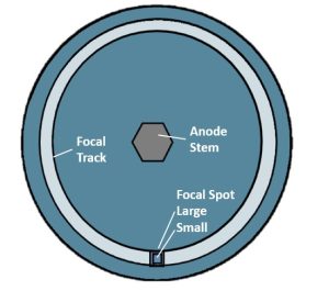
Figure 1-5: The Rotating Anode


The anode is shaped like a saucer. When visualizing how the anode sits in the x-ray tube, think of a saucer standing on end with its bottom facing the filament wires (Figure 1-5). The edge of the anode that tilts back is where the x-rays are produced. The anode rotates while the x-rays are being produced so that the production of x-rays takes place all around the edge of the anode in an area called the focal track. If we took a snapshot of the process of x-ray production, the exact area that the electrons strike along the focal track is called the focal spot or target.
Figure 1-6: Layers of the Anode Disk
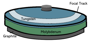
The top layer of the anode is made of tungsten. The layer of tungsten is bonded to a molybdenum disk. Molybdenum inhibits heat transfer from the surface of the anode to help prevent damage to the rotor. Some anodes are also backed with a layer of graphite.
The modern anode (Figure 1-6), which is the positively charged electrode, is a disk made of molybdenum and coated with tungsten, which has a little rhenium added to it. Tungsten has a high atomic number, which is important for efficient x-ray production, and a high melting point that helps it endure the extreme temperatures that can occur during x-ray production. The rhenium serves to reduce cracks and surface imperfections in the anode disk. The molybdenum prevents the heat produced by the electron interactions from traveling down the stem of the anode and warping the bearings that allow the anode to rotate. Graphite keeps the anode from cracking when it experiences rapid changes in temperature.
Key Takeaways
The positively charged anode:
- Accelerates the emitted electrons, AND
- Stops the accelerated electrons, causing kinetic energy to be converted to x-rays.
The anode has two roles in the production of x-rays. First, the positive charge applied to the anode creates a potential difference, or voltage, that further accelerates the electrons released by the filament. The voltage applied to the x-ray tube during the creation of x-rays is typically between 60,000 and 120,000 volts! This extremely high voltage causes the electrons crossing the tube to reach speeds nearly equal to the speed of light!!!! Newton’s Second Law of Motion tells us that even though an electron has a really small amount of mass, a high rate of acceleration can still cause it to produce a high amount of force, which we typically think of in terms of kinetic energy. This brings us to the second role of the anode – to stop those speeding electrons! When we bring those electrons to a stop, all that extra energy has to go somewhere – The Law of Conservation of Matter and Energy tells us that matter and energy can be neither created nor destroyed, only changed from one form to another. When we stop those speeding electrons we convert the kinetic energy that the electrons had acquired while crossing the x-ray tube into electromagnetic energy – x-rays.
The anode rotates to help spread out the heat created by the electron interactions at the target. The anodes in standard x-ray tubes typically rotate at around 3,000 rpm. For radiographic examinations that require high tube current (lots of electrons hitting the anode) or exams where multiple exposures are made in a very short amount of time (like CT scanners), high speed rotating anodes with rotational speeds of about 10,000 rpm are used.
The Glass Envelope
The inside parts of the x-ray tube (the cathode, containing the filament and focusing cup, and the anode) are surrounded by a glass housing made of Pyrex glass (Figure 1-7). The glass housing has a thin spot in it called the window. This Pyrex glass has lead added to it. The lead helps to absorb any leakage radiation, i.e. radiation that tries to go any direction but through the window.
The x-ray beam is produced at the anode and first exits the tube through this window before it travels toward the patient’s body.While the x-ray tube is being manufactured it is baked, and this removes the air inside the glass housing, creating a vacuum. As mentioned earlier, the vacuum is important to getting consistent amounts of x-rays produced during the exposure. If the glass envelope cracks, the vacuum is destroyed and it’s time to buy a new x-ray tube.
Figure 1-7: The Modern Glass Enclosed X-Ray Tube
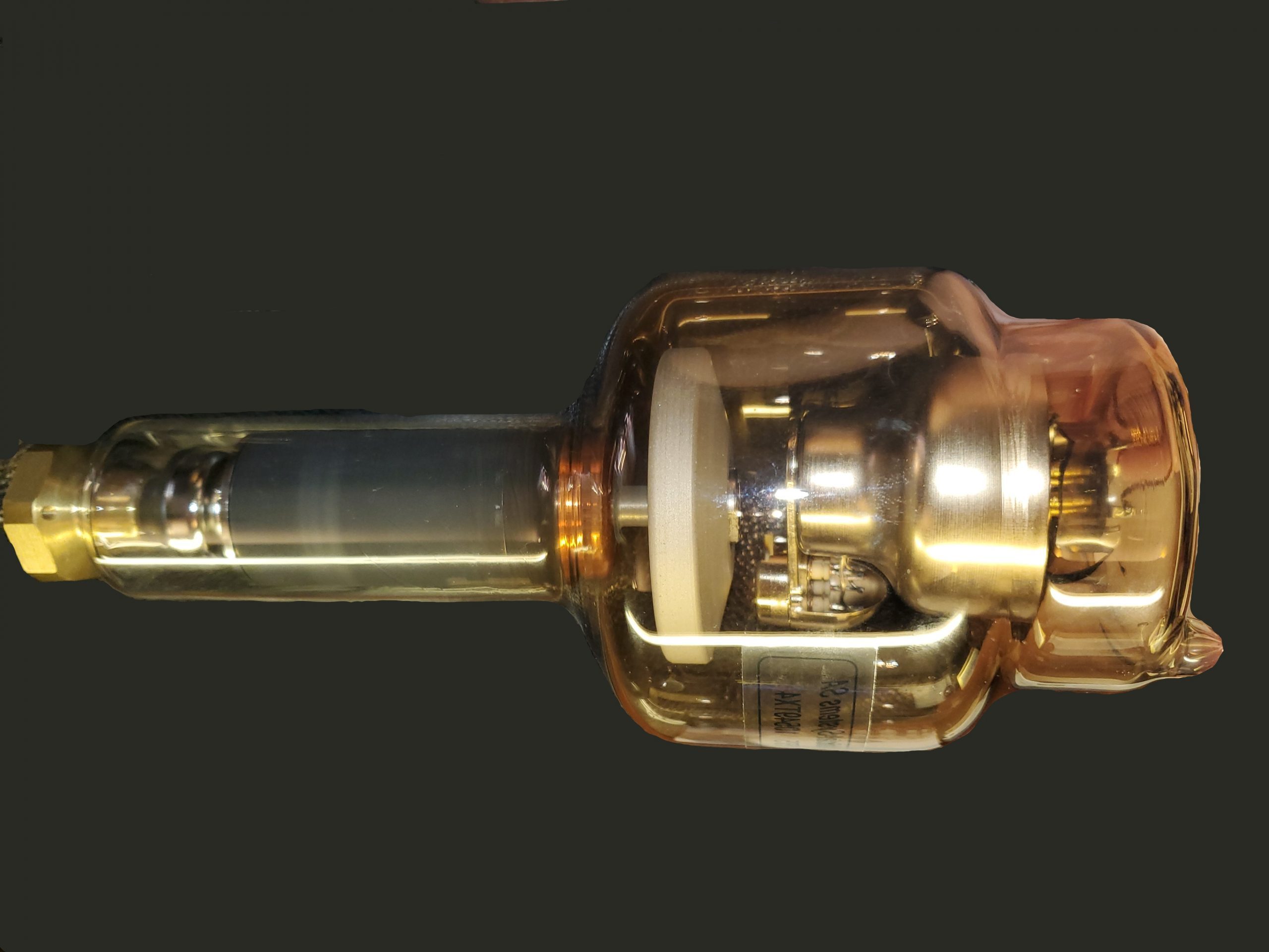
Figure 1-8: The X-Ray Tube within its Metal Housing.
The Metal Housing
A metal housing is built on the outside of the glass envelope. One of its purposes is to protect the glass envelope. The metal housing is what the radiographer sees when looking at the x-ray tube. The insides of the tube and the glass envelope are hidden by this metal housing. At first students often confuse the collimator box with the tube. The x-ray tube sits above the collimator box (Figure 1-8).
Production of the X-Ray Beam
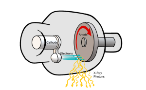
Now that we know about the individual components of the x-ray tube and their roles, let’s examine the production of the x-ray beam in a little more detail. X-rays are produced inside the x-ray tube after a chain of events involving the filament, focusing cup and anode. The chain of events involves releasing electrons from atoms at the filament, giving the released electrons a high speed, focusing these electrons, and the stopping them suddenly at the anode where the x-rays are produced (see Figure 1-9).
Figure 1-9: Production of the X-Ray Beam
Releasing the Electrons
The first event is the removal of electrons from the atoms contained in the filament wire. The filament is the source of the electrons. The filament wires are connected in a circuit, which is a group of wires that can conduct electricity. The circuit containing the filament wires is called the filament circuit. The number of electrons flowing in a circuit is described by the term current. When current is sent through this circuit, one of the two filament wires heats up. The more electrons that flow through the filament, the hotter the filament wires get.
Key Takeaways
The filament wires are made of tungsten, which has a high melting point. The high melting point is important because the current causes the wire to get hot enough to actually glow. This glowing is called incandescence. When the filament gets this hot, electrons are “boiled off” or freed from the atoms of the filament. This process of releasing electrons is called thermionic emission – “therm-” meaning heat and “-ionic” meaning a charged particle, in this case an electron. Because the temperatures necessary for thermionic emission in tungsten are very near its melting point, reaching thermionic emission can put us at risk of melting the filament wire, resulting in catastrophic failure of the x-ray tube. To help reduce the risk of melting the filament wires, we can add a little bit of thorium to the tungsten. The thorium causes thermionic emission to take place at significantly lower temperatures and keeps us from reaching the melting point of tungsten under normal circumstances.
Figure 1-10: Electron Cloud or Space Charge
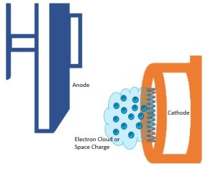
For a fraction of a second these electrons sit right beyond the filament in a group called the electron cloud or space charge (Figure 1-10). All electrons are negatively charged, and since like charges repel each other, the electrons in this group want to spread out away from each other. So, the focusing cup is used to hold the group of electrons together.
Focusing the Electrons
The focusing cup helps the electrons hit the anode in a small area.
Key Takeaways
The focusing cup surrounds the filament on three sides. It is the role of the focusing cup to compress the electron beam as it crosses the x-ray tube. See Figure 1-11. The cup is made of nickel and is negatively charged. Because like charges repel each other, the negative charge on the focusing cup repels the electrons that are emitted from the filament, keeping them from spreading out across the x-ray tube. The repulsive action of the focusing cup also serves to propel the stream of electrons away from the cathode and toward the focal spot on the anode.
Figure 1-11: Focusing the Electron Cloud
Accelerating the Electrons to High Speed
The electrons must travel from the cathode to the anode at high speeds to produce x-rays. Two forces work together to produce this high speed. During the exposure, the focusing cup gets a strong negative charge and the anode gets a strong positive charge. The negatively charged electrons sitting in their group (the space charge) just beyond the filament are repelled by the negatively charged focusing cup. This causes the electrons to leave the filament as a group and shoot over to the anode. While the negative charge of the focusing cup starts the electron stream moving, the pull of the anode is primarily responsible for the high speeds the electrons reach (Figure 1-11).
The high kilovoltage (thousands of volts) applied to the x-ray tube causes the anode to have a very high positive charge. Because the anode has this high positive charged, and opposite charges attract, the positive anode pulls the negative electrons from the filament at the same time that they are being repelled by the focusing cup. This combination of push and pull forces the electrons to travel at high speed between the filament and the anode. The high speed gives the electrons a large amount of kinetic energy, which is the energy of motion.
Stopping the Electrons and Creating X-rays
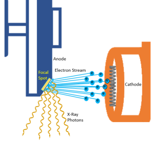
The actual place that the electrons hit on the surface of the anode is called the target. The anode disk is made of molybdenum, which is coated with tungsten so the anode surface or the target area is made of tungsten. The size of the area that the electrons hit is called the focal spot (Figure 1-11). The anode disk, the target and the focal spot are all physically located in the same place (at the anode), but the terms should not be interchanged since they each mean something different.
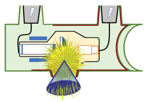
Figure 1-12: Isotropic Emission of X-Rays
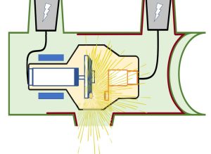
X-rays are emitted from the focal spot in all directions. This is called isotropic emission. The tube housing absorbs the radiation that is directed at any angle other than through the window.
When the x-rays are produced at the focal spot, they fly off in all directions, like the sparks from a Fourth of July sparkler. This spherical pattern is called isotropic emission (Figure 1-12). Only the x-rays that are aimed at the patient are useful to us. The rest of the x-rays could fly out of the tube and hit people other than the patient. This is why a lead glass envelope and a lead-lined metal housing are put around the cathode and anode. These housings and the anode disk absorb this unnecessary radiation. A tiny bit of radiation still might get through, and this is called leakage radiation. Leakage radiation is limited to no more than 100mR/hour at 1 meter.
Activity 1A – X-Ray Components Crossword
Use this crossword puzzle to test your knowledge of the components of the x-ray tube.
Activity 1B – The Process of X-Ray Production
Place the steps in the production of x-rays in the correct order.
Electron Interactions with Target Atoms
The wavelengths and energy levels of the x-rays in the beam are determined by the specific interactions of the electrons with the atoms in the anode. Atoms with a high atomic number will have much larger nuclei and a LOT more orbital electrons with which the high-speed electrons from the cathode may interact. Because there is more for the high-speed electrons, i.e. incident electrons, to interact with, a lot more interactions occur and those that do occur will result in the production of higher energy x-rays. This is the primary reason Tungsten (atomic number 74) is chosen as the target material on the anode.
When the electrons slam into the anode at high speed, they interact in one of three locations: with an outer shell orbital electron, with an inner shell orbital electron, or with the nucleus. What gets created depends on where the incident electron interacts.
Outer Shell Interactions
When the incident electron (i.e. an incoming electron or electrons emitted at the filament) interacts with an outer shell electron, energy is transferred from the high-speed electron that causes the outer shell electron to become excited. When the outer shell electron absorbs more energy that the binding energy that keeps it in its orbital, it jumps up to the next higher electron shell. However, it leaves a vacancy in its normal orbital. To return to its normal orbital, the excited electron releases the excess energy in the form of infrared radiation – heat. 99% of all incident electron interactions create heat.
Key Takeaways
Electron interactions with outer shell orbital electrons in the target create heat.
While we don’t typically think of heat as similar to light, infrared radiation is actually part of the electromagnetic spectrum. It just has a much longer wavelength and a much lower energy than x-rays.
Inner Shell Interactions
Some incident electrons make it past the outer shell and interact with inner shell electrons. To understand these interactions that occur between the incident electrons and inner shell electrons of the target atoms, we need to understand electron binding energies – the energy that keeps the electrons in place around an atom.
Electron Binding Energy
We know that electrons are contained in orbitals or shell in organized levels around the nucleus. Because the nucleus has a positive charge and electrons are negative, there is a force attracting the electrons toward the nucleus. We call this attractive force electron binding energy because it binds the electrons in place – keeping them in their orbital shells.
The electron binding energy on a particular electron is dependent on two factors: how many protons are in the nucleus and how far the orbital electron is from the nucleus. The number of protons in the nucleus is an important piece of information about an atom because it determines the chemical properties of the element and its place in the periodic table. This means that the electron binding energies are different for atoms of each different element. The orbital electron’s distance from the nucleus is defined by its orbital shell. When physicists talk about the electron shells, they label them with letters, starting with the letter K. The reason orbitals start with the letter K and not A has a humorous story behind it. Physicist Charles G. Barkla was one of the early scientists studying x-ray production. He had noticed that there were two different energy levels of x-rays emitted from the atoms struck with high speed electrons. He started off talking about the x-rays with the highest energies as type A x-rays and the lower energy x-rays as types B, C, etc., but he wasn’t sure that the type A x-rays were the highest energy x-rays possible. Since he wanted to leave room in his labeling scheme for the discovery of even higher energy x-rays, he changed the name of the highest energy x-rays he had identified to type K. It turns out that k-type x-rays were the highest energy x-rays possible with this type of interaction, but by that time the name had stuck. So the highest energy x-rays are called K x-rays and the electron shell that the x-rays are emitted from, which happens to be the electron shell closest to the nucleus is called the K-shell. See Figure 1-13 for a Bohr model of a tungsten atom with labeled shells.
Figure 1-13: Bohr Model of a Tungsten Atom
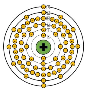
Tungsten has an atomic number of 74 and is surrounded by 74 electrons. The shells are labeled starting at K from the inside out.
In the interaction between an incident electron and an inner shell electron, the high-speed electron passes near an inner shell orbital electron. Because both electrons have a negative charge and like charges repel, the repulsive force between the two electrons ejects the orbital electron from its orbit. This leaves a vacancy in the inner orbital, which makes the atom unstable. In order to become more stable one of the outer shell electrons drops into the inner shell to fill the vacancy. Because outer shell electrons have more energy to fight the attractive force of the positive nucleus, the outer shell electron has to lose energy to move into the inner shell vacancy. The energy that the outer shell electron loses is released as an x-ray. We call this x-ray characteristic radiation because the energy of the emitted x-ray is characteristic of the difference between the binding energies of the shell the orbital electron came from and the shell it dropped into (see Figure 1-13).
Figure 1-13: Characteristic Interactions
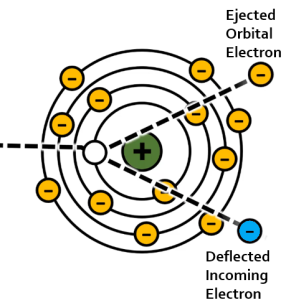
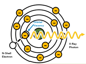
Characteristic interactions happen in 2 steps. In the first, the incident electron from the filament interacts with an inner shell electron, ejecting it from its orbit. In the second step, an outer shell electron loses energy in the form of a characteristic x-ray so that it can drop into the inner shell vacancy.
Characteristic radiation makes up a small portion, less than 15%, of the total x-ray beam. Characteristic x-rays are completely dependent on the difference in energy levels between the orbits in the atom. Since the binding energies for each orbital level are known for each element, we can accurately calculate the energy of each characteristic x-ray produced. For tungsten atoms, the innermost orbital electrons have a binding energy of 69.5 keV. Since the more distant orbitals have binding energies ranging from 0.5 to 12 keV, we can expect all characteristic x-rays produced in a tungsten target to have energies between 57.5 and 69 keV.
Key Takeaways
If we graph the number of characteristic x-ray photons at each energy level, we will see a series of vertical lines. These lines will be clustered into two groups, one for x-rays released by electrons filling L-shell vacancies and another for x-ray released by electrons filling K-shell vacancies (See Figure 1-14). We call graphs of the number of photons at each energy level emissions spectra. When referring to the shape of the emissions spectra created by characteristic x-rays, we use the term “discrete” because each spike stands separately from the next one. While we can get characteristic interactions occurring when vacancies are filled further from the nucleus, the energy is so low that the photons released are ultraviolet light rather than x-rays.
Figure 1-14: Characteristic X-Ray Emission Spectra
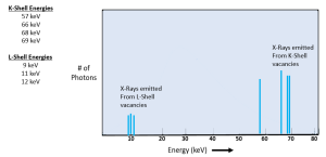
This graph of the characteristic x-ray energies separates the individual energy spikes. When measuring the actual x-ray output, it can become difficult to distinguish between very closely placed energy spikes. Some emission spectra will illustrate single spikes.
Interactions with the Nucleus
If the high-energy electron passes near the atomic nucleus of the target atom, the positive attraction of the nucleus will cause the electron to slow down or brake (See Figure 1-15). As Roentgen discovered and characterized x-rays in Germany, he applied a German term to this interaction – Bremsstrahlung. Bremsstrahlung means braking in German. When the electron slows down, it is, in essence, losing kinetic energy. We know that the lost energy does not simply disappear, it has to be converted to something else. In this instance the kinetic energy lost by the electron is released as an x-ray photon. Bremsstrahlung radiation accounts for more than 85% of the total number of x-rays in the beam.
Figure 1-15: Bremsstrahlung Interactions
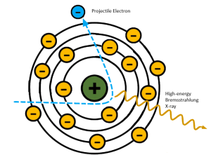
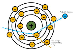
Projectile electrons that slow down a lot make sharper turns and lose more energy. Projectile electrons that only slow down a little don’t change direction as much and lose less energy.
Because the incident electrons can pass the nucleus at different distances, the amount of deceleration varies. The closer an electron passes to the nucleus, the greater its deceleration will be. Because Bremsstrahlung interactions take place at these different distances, it is these interactions that are responsible for the heterogeneous or poly-energetic nature of the x-ray beam. A heterogeneous x-ray beam is necessary because it is what makes differential absorption possible. In differential absorption, tissues that are more dense or have higher atomic numbers will absorb more x-rays than tissues that are thinner or made of lower atomic number atoms. If all of the x-rays in the beam were the same energy, the radiograph would not show different shades of gray. It would only show black or white. More on this in Chapter 2. A wide variety of x-ray energies are essential to properly demonstrating the subtle differences in tissues.
Key Takeaways
The distance the electron will pass from the nucleus is a function of statistical probability. We know that the incident electron is more likely to pass through an atom further away from the nucleus and less likely to pass near it. Because electrons passing further from the nucleus do not slow down very much, they emit lower energy x-rays. As the electrons pass closer to the nucleus the energies of the emitted x-rays increases. The probabilities tell us that more low energy x-rays will be produced than high energy ones. Plotting the relationship between the photon energy levels and number of x-ray photons produced at that energy will produce a bell-shaped curve with the greatest number of photons occurring at approximately 1/3 of the highest energy level (See figure 1-16). Notice that all possible energy levels are represented on the bremsstrahlung emissions spectra. We call this type of graph continuous, because there are no breaks in the possible energies of the photons. The highest energy on the bremsstrahlung graph is determined by the kilovoltage selected by the radiologic technologist. For example, if a technologist selects 120 kVp for a PA chest x-ray, the highest possible energy of any bremsstrahlung x-ray will be 120 keV.
Figure 1-16: Bremsstrahlung Emission Spectra
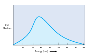
Bremsstrahlung x-rays have continuously variable energies with the greatest amplitude occurring at approximately 1/3 of the kVp used to create the beam.
Emissions Spectra of the entire Beam
When we combine the graph of the Characteristic radiation energies with the graph of the Bremsstrahlung radiation energies, we get a complete picture of both the number and energies of the x-rays in the beam (Figure 1-17). The amplitude of the bell-shaped brems curve gives us an idea of the total number of x-rays in the x-ray beam. The position of the characteristic spikes indicate the material the anode target is made of. The left-to-right position of the brems curve indicates the median energy of x-ray photons in the beam.
Figure 1-17: The Complete Emission Spectra
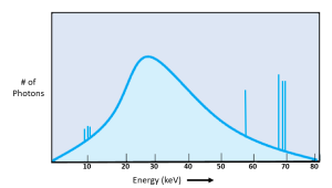
The number of characteristic x-rays gets added to the number of bremsstrahlung x-rays emitted at the same energy level.
Activity 1C – Match the Diagrams
Match each diagram with its description.
Properties of X-rays
After the x-rays are produced they have some properties that are important to understand because the properties affect the quality of the radiograph. The properties also help determine what technical factors the radiographer should use to produce a good radiograph. The properties that are listed in this book are not all the x-ray properties, but they are the ones that pertain to radiographic quality.
X-Ray Property
That x-rays travel in straight lines is a principle quality that we use in the design of our rooms and radiation protection practices. We can be assured that we are safe behind the control panel of our x-ray rooms, even with an open doorway next to us as long as there is no direct line between the radiation source and us. The x-rays cannot turn corners. From the standpoint of image quality, the fact that x-rays only travel in straight lines is what enables us to produce an image that accurately represents the patient’s body.
X-Ray Property
The part of the x-ray beam that is directed at the patient is only a section of the x-rays produced at the anode (Figure 1-18). Since the remainder of the x-rays are absorbed by the anode, the glass envelope and the tube housing, they are virtually eliminated. The x-rays that are aimed at the patient are still moving away from the focal spot. They all keep traveling in straight lines, but because they are still moving isotropically, they diverge or move away from each other, creating a cone-shaped beam.
Figure 1-18: Diverging Photons Create a Cone-Shaped Beam
X-Ray Property
The x-ray beam that is directed at the patient consists of millions of x-rays or what are better called x-ray photons. A photon is a tiny particle of energy. The energy of each of the photons in the x-ray beam can be different. The technical term for this is heterogeneous or polyenergetic.
Figure 1-19: The Heterogenous Beam
X-Ray Property
Photons with less energy are absorbed more easily by the patient’s body parts, whereas photons with more energy will penetrate right through the patient’s body. The photons that get through the patient’s body will hit the image receptor and eventually produce an image of the patient’s body.
X-rays are a form of electromagnetic radiation. There are many different kinds of electromagnetic radiation, such as radio waves and light waves, but x-rays are a type that is able to penetrate through matter such as the patient’s body.
X-Ray Property
Since x-rays are a type of energy, they are invisible. This can make them seem mysterious and is why many people are afraid of them. X-rays cannot be seen as they are produced, as they leave the x-ray tube, or as they enter the patient’s body. It’s obvious that they were there, though, when the image of the patient’s body appears on the radiograph.
X-Ray Property
The speed of light is 3 x 10⁸ meters/second or approximately 186,000 miles/second, and x-rays travel at the same speed as light. The walls in an x-ray room are lined with lead, which is good at absorbing x-rays. The radiographer stands in a lead-shielded area when making the exposure, and since x-rays travel so fast, they will already be absorbed by the lead in the walls by the time the radiographer lets go of the exposure button and gets back inside the x-ray room.
X-Ray Property
Scattered radiation is produced when x-rays enter the patient’s body. The x-ray beam that is directed at the patient’s body is called the primary beam (Figure 1-20). When the primary beam enters the patient’s body, three things could happen to the photons:
- Photons could be absorbed by the patient’s body parts.
- Photons could pass right through the patient’s body and enter the image receptor, depositing energy to create the image. These photons are called exit radiation or remnant radiation.
- Photons could hit something in the patient’s body, bounce off, and fly out in a new direction. These photons are called scattered radiation.
Figure 1-20: Primary, Remnant and Scattered Radiation
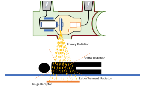
Scattered radiation that hits the image receptor creates several significant problems for the quality of the radiographic image. Scatter reduces radiographic contrast. Loss of contrast is not good, and there are a variety of things the radiographer can do to avoid the problems associated with scatter. We will examine ways to counteract the effects of scatter radiation in future chapters.
X-Ray Property
X-rays produce an image of the patient’s body by affecting the image receptor. When x-ray photons hit the image receptor, they interact with the atoms in the receptor and knock some electrons out of place. The removal of an electron from a neutral atom creates an ion pair – a positively charged atom and a negatively charged electron. The process of creating this ion pair is called ionization.
Ionization is a key factor in the creation of the radiographic image. The ionization that takes place in the image receptor produces electrical pulses that are measured to determine the amount of remnant radiation interacting with a specific location within the image receptor. The computer then assigns a shade of gray to that portion of the image based on the level of ionization that occurred there. Areas of the image receptor that absorbed a lot of radiation will have a higher electric charge and will be displayed as darker or black areas on the image. Areas of the image receptor that receive low levels of x-rays will have low electric charges and will be displayed as brighter or white areas on the image. The variation in levels of brightness seen on the radiograph is called contrast.
X-Ray Property
X-rays can cause certain materials called phosphors to glow or light up. This glowing is called fluorescence. The phosphors light up in proportion to the amount of radiation that hits them. If a large quantity of radiation hits a phosphor, that phosphor lights up very bright. If only a little radiation hits the phosphor, the phosphor gives off only a little light. Fluorescent materials can be used to magnify the action of x-rays in the creation of the radiographic image.
When x-rays interact with a fluorescent phosphor, the phosphor crystals glow. The light given off by the phosphor crystals can cause other materials to release electrons. Because each x-ray can cause the phosphor to release many light photons, a greater electric charge can be produced
X-Ray Property
The x-ray properties we have been discussing so far are all fascinating and exciting! This last one isn’t so great for us or the patients. X-rays can damage biological or living matter. X-ray photons can change the atoms in the living body to leave some of the atoms in the body. Remember that this process of removing an electron from an atom is called ionization. When ionization happens inside living tissues, the chemical changes that occur can damage the DNA in the cells. This can cause the cell to either die or malfunction. If DNA damage occurs in sperm or ova that are then used to produce a baby, the damage can be transferred to the baby’s body. This is why radiographers must be so careful about protecting themselves, their patients, and others from unnecessary radiation.
- X-rays travel in straight lines.
- X-rays diverge from their point of origin at the focal spot.
- X-ray photons have many different energies.
- X-rays are highly penetrating.
- X-rays are invisible.
- X-rays travel at the speed of light.
- X-rays produce scattered radiation.
- X-rays ionize matter.
- X-rays cause fluorescence of some materials.
- X-rays cause biological damage.
In addition to the 10 properties listed above, x-rays have other properties that do not have an impact on radiographic image quality. These include:
- X-rays have no mass.
- X-rays have no charge. They cannot be deflected by electric or magnetic fields.
- X-rays cannot be focused with a lens.
- The are capable of traveling in a vacuum. (Which is a good thing since we are creating them in a vacuum!)
Activity 1D – X-Ray Properties Word Find
Decide which word best matches the definition or completes the sentence, then find it in the word search puzzle and circle it.
- Can you see x-rays? They are __________
- One word meaning many energies
- Another word meaning many energies
- ____________ radiation is directed at the patient.
- X-rays travel at the speed of __________.
- Low energy x-rays are more easily ____________ by the patient’s body.
- X-rays are highly ______________.
- X-rays are emitted in all directions. This is called ______________ emission.
- X-rays __________ from the focal spot.
- X-rays cause _______________ damage.
- X-rays are a form of _____________________ radiation.
- The process of removing electrons from atoms.
- This type of radiation gets through the patient and deposits energy in the image receptor.
- X-rays travel in ______________ lines.
- X-rays cause __________________ of some materials.
- X-rays that bounce off the patient’s body are called __________
Summary
The inside parts of the x-ray tube are the anode and the cathode. The cathode consists of the focusing cup and filament. When x-rays are produced, electrons are released from the filament, given a high speed, and focused into a small group by the focusing cup. When they zoom over to the anode, they are stopped suddenly. The kinetic energy of the electrons is converted to x-rays. X-rays are created by two different types of interactions with target atoms. When the incident electron ejects an inner-shell electron and an outer-shell electron drops in to fill the vacancy, a characteristic x-ray is released. Characteristic x-rays have discrete energies and are graphed as vertical lines. When the incident electron passes the nucleus of the target atom and changes direction because of the attractive pull of the nucleus, the incident electron loses energy in the form of a bremsstrahlung x-ray. Bremsstrahlung x-rays have continuous energy ranges and are graphed as a bell-shaped curve. X-rays have certain properties. These properties are summarized in Table 1-1.
Kilovoltage peak; determines the energy and penetrating ability of the x-ray beam
The weighted combination of all of the visually significant characteristics of an image that contribute to the diagnostic value of the image.
The sharpness of the lines of the structures included in the image. Recorded detail is related to the concept of spatial resolution.