2 From X-Ray Beam to Image Signal
In this chapter you will learn about the properties of the x-ray beam and how it’s properties change as it passes through matter. A satisfactory understanding of what takes place with the x-ray beam on its way to the image receptor is essential to understanding how changes in technical factors alter the beam’s properties and the resultant display image.
Learning Objectives
At the end of this chapter you should be able to:
- Differentiate between Source-Image Distance, Object-Image Distance and Source-Object Distance.
- Calculate SID, OID or SOD when given the two other factors.
- Differentiate between primary radiation and remnant radiation.
- Define attenuation.
- Explain the role electron binding energy plays in the interactions of x-rays with matter.
- Explain the interactions between x-rays and matter that occur at diagnostic ranges – Photoelectric effect and Compton Scattering
- Differentiate between secondary radiation and scatter.
- Discuss the factors that contribute to differential absorption.
- Define subject contrast.
- Differentiate between radiolucent and radiopaque tissues.
Key Terms
When a radiographic exposure is made, x-rays are produced from a small area of the anode called the focal spot. The x-rays diverge outwards from this area, travel in straight lines, and can be detected by a variety of image receptors. We frequently discuss portions of the x-ray beam in relation to the object that is being imaged. When the x-ray beam passes through the body, some photons in the beam will be absorbed by the tissues and organs, while other photons will pass through to the image receptor and form the basis for the creation of the display image.
Radiographic Geometry
Before learning about the factors that influence the accuracy of the radiographic image, it is important to learn some basic terminology associated with distances. For many radiographic studies, the patient lies flat on the x-ray table. The x-ray tube is positioned above them and the image receptor is placed in the Bucky tray below them. See Figure 2-1.
The distance between the x-ray tube and the patient can be measured, as can the distance between the patient and the image receptor. We can also measure the distance between the x-ray tube and the image receptor. These distances are important and have specific names.
Figure 2-1: Radiographic Distances
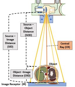
This diagram illustrates the various components of an x-ray beam with relation to an object (and objects internal to that object) and an image receptor.
Source-Image Distance
The distance between the x-ray tube and the image receptor is known and the source-image distance (SID). This distance is called the source-image distance because it is the distance from the source of the x-ray beam, which is in the x-ray tube, to the spot where the image is formed, some type of image receptor. This distance can also be called the source-to-image receptor distance.
Object-Image Distance
The patient is inelegantly referred to as the object in these distance terms. However, referring to the patient as the object is not always precise. The patient’s body is a three-dimensional structure. If the radiographer is interested in producing a radiography of just one part inside the patient, the that part becomes the object.
The distance between the part inside the patient’s body that is being radiographed and the place where the image is formed, which is usually at the image receptor, is known as the object-image distance (OID).
Source-Object Distance
The last distance is the distance from the x-ray tube to the object. This distance is called the source-object distance (SOD). This term is used less frequently in clinical situations than SID or OID, but it is used in several calculations.
Calculating the Distances
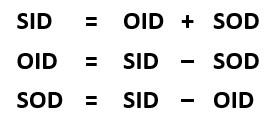 If two of these three distances are known, the other one can be calculated. Refer to the formulas on the left. If the source-image distance (SID) is 40 inches and the object-image distance (OID) is 4 inches, the source-object distance (SOD) can be calculated by subtracting the OID from the SID. The SOD is 36 inches. Adding the OID of 4 and the SOD of 36 gets the SID of 40. And subtracting the SOD of 36 from the SID of 40 gets the OID of 4.
The X-ray Beam
When we discuss the x-ray beam, we typically think of the properties of the beam in terms of 2 concepts – quantity and quality.
Quantity
Beam quantity refers to the number of x-rays in the beam. That makes sense, but another term that is used to refer to quantity is intensity. In normal speaking we think of intensity as synonymous with power. For the x-ray usage, that doesn’t work. Let us think about intensity of the x-ray beam by thinking about a flashlight. When someone shines a flashlight in your eyes, the brightness, or intensity of the flashlight is dependent on the number of light photons being given out. If your battery is dying and your flashlight beam is less intense, then fewer light photons are being produced.
We can see x-ray quantity on the emission spectra of the x-ray beam. See Figure 2-2. When the quantity of x-rays in the beam changes, the amplitude of the graph moves up or down. In Figure 2-2, the x-ray beam represented by the pink line has a lower quantity or lower intensity than the x-ray beam represented by the blue line. Notice that the characteristic peaks move up or down as well as the overall brems curve. The primary factor that we use to control the quantity of the beam is mAs. Remember from our discussion of the production of x-rays that the number of electrons flowing through the filament controls the number of electrons that boil off and travel across the tube to make x-rays. We control the number of electrons flowing through the filament by the mAs we set. mAs stands for milliampere-seconds. This is because both mA (milliamps or the number of electrons flowing) and the time we let the electrons flow for (in seconds) both affect the number of x-rays created in the same way – double the mAs = double the # of x-rays.
Figure 2-2: Quantity of the X-ray Beam
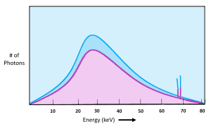
The pink curve represents an x-ray beam with fewer x-rays in it. We would say that the pink x-ray beam has lower quantity or lower intensity than the beam represented by the blue curve.
Quality
The other idea we use to talk about the x-ray beam is its quality. The quality of an x-ray beam refers to its penetrating ability. We primarily control the quality of the x-ray beam using kVp. kVp is the potential difference or pull we use to accelerate the electrons from the filament to the anode. The faster we accelerate the electrons, the more kinetic energy they acquire.
Electrons with more kinetic energy when they slam into the anode produce higher energy x-rays .
We can see the quality of the x-ray beam on the emission spectra as well. See Figure 2-3. We see changes to the beam quality on the emission spectra as shifts to the left or to the right. When comparing the two x-ray beams represented in Figure 2-3, the blue beam extends further to the right and the top peak of the graph is also more to the right than the red beam. However, when we use kVp to change the quality of the beam, we also get a change in quantity. We see the change in quantity on the graph because the top of the blue line is higher than the red line.
Figure 2-3: Quality of the X-Ray Beam
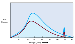
Quality of the x-ray beam is represented by the left-right position of the graph. kVp is the primary controlling factor, but kVp affects both quality and quantity.
X-Ray Beam Before and After the Patient
The x-ray beam may be divided into two parts, the primary beam and the remnant beam. See Figure 2-4.
Figure 2-4: Primary and Remnant Radiation
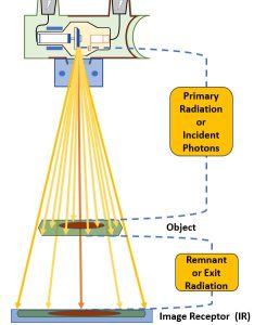
The x-ray beam as it is emitted from the focal spot is referred to as primary radiation. When the x-ray beam passes through matter it undergoes attenuation. The portion of the x-ray beam that exits the patient and continues on to deposit energy in the image receptor is discussed as remnant or exit radiation.
Primary Radiation
The primary radiation is confined to the portion of the x-ray beam emitted from the focal spot of the x-ray tube. The radiation in the primary beam stays essentially the same from the point it is emitted from the x-ray tube until it encounters the object being examined. We also use the term incident x-rays or incident photons to refer to individual x-rays in the primary beam. Incident is a term that means “falling on or striking something,” so electrons crossing the tube and striking the anode are incident electrons and x-rays crossing the room and striking the patient are incident x-rays. The terms photon and quantum (or quanta in plural form) are referring to a single bundle of electromagnetic energy, i.e. a single x-ray. The terms photon and quantum also carry the idea of x-rays as a small particle. This is due to an interesting characteristic of x-rays- while they are electromagnetic waves, they sometimes behave as particles, even though they have no mass. This is the concept of wave-particle duality, and the reason x-rays can interact with matter at all. Wave-particle duality also applies to other high-energy forms of electromagnetic energy, such as gamma rays and cosmic rays.
Remnant Radiation
The remnant radiation (also sometimes referred to as exit radiation) is that portion of the primary beam that emerges from the examined object and interacts with the image receptor to record the radiographic image. But not all of the photons contained in the primary beam make it out of the object being examined. Some interact with the atoms in the organs and tissues inside the patient and are absorbed. So, the remnant beam is what remains of the primary beam after the number of x-ray photons in the beam are diminished through absorption by the body tissues.
When using typical diagnostic exposure factors, only about 5% of the x-ray beam travels through the patient’s body without interacting and deposits energy in the image receptor to create the image.
Absorption vs. Attenuation
When x-rays pass through an object, some of the x-ray photons interact with atoms in the object and are no longer part of the x-ray beam. The reduction in the number of x-rays in the beam due to these interactions is called attenuation. See Figure 2-5. Attenuation occurs when an incident photon is either absorbed by the atoms of the tissue or scattered in another direction. There are five types of interactions that may occur between photons and the atoms in their path – Coherent or classical scattering, Compton Scattering, Photoelectric Absorption, Pair Production, and Photodisintegration. However, when dealing with x-ray energies that are typically found in diagnostic imaging x-ray beams, only two of these interactions routinely occur – Photoelectric Absorption and Compton Scattering.
Figure 2-5: Attenuation of the Beam
Electron Binding Energy
In order to understand the interactions of x-rays with matter we need to revisit the concept of electron shells and electron binding energy. You should recall from our discussion of the interactions that create x-rays inside the x-ray tube that atoms are surrounded by electrons that are positioned at specific distances from the nucleus called shells. These shells are labeled from the innermost shell outward starting with the letter K (See Figure 2-6). The positively charged nucleus exerts an electric force of attraction on the orbital electrons and the force is greater the closer the electron shell is to the nucleus. Because of the higher binding energies of electrons closer to the nucleus, it takes more force to remove an electron from the K-shell than is does to remove an electron from one of the outer shells. Because it takes energy to fight the attractive force of the nucleus and allow the electron to maintain a position further from the nucleus, the electron itself has higher energy the further from the nucleus that it exists. The energy of the orbital electron is inversely proportional to the binding energy attracting it to the nucleus. This means that electrons in the O or P shells maintain higher energy levels than electrons in the K-shell.
While the tungsten atoms found in the x-ray tube have a very high atomic number and lots of electrons around them, most of the elements that make up the tissues in our bodies are much smaller. For example, a major element in our bones is calcium. Calcium has an atomic number of 20, and is therefore surrounded by 20 electrons. Because there are much fewer protons in a calcium nucleus the force holding electrons in each shell is much lower.
Figure 2-6: Bohr Model of a Calcium Atom
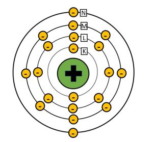
Calcium, which has an atomic number of 20, has 20 electrons surrounding the nucleus. Because the nucleus of calcium has a lower positive charge than tungsten, the binding energies holding the electrons in their shells are much lower.
Photoelectric Absorption
Photoelectric absorption, or the photoelectric effect, is essential to the formation of the radiographic image. The photoelectric effect takes place when the energy of the incident x-ray is just slightly greater than the binding energy holding the electron it collides with in place. In the process of photoelectric absorption, the energy of the x-ray photon is completely absorbed by an inner shell orbital electron. This added energy gives the electron the force needed to escape the binding energy of the nucleus and the electron is ejected from orbit. See Figure 2-7. We call the electron that is ejected from orbit during photoelectric interactions a photoelectron. The photoelectron will eventually collide with and ionize another nearby atom.
Figure 2-7: Photoelectric Effect
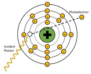
In photoelectric effect the energy of the incident x-ray is completely transferred to the inner shell electron and used to overcome the electron binding energy and propel the orbital electron away from the atom. The x-ray is completely absorbed in this process. The ejected electron is called a photoelectron.
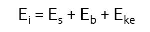
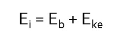 The energy transfer involved in photoelectric interactions can be described by the mathematical equation seen here (left). In this equation we see that Ei, the energy of the incident photon, is distributed between Eb, the binding energy of the orbital electron and Eke, the kinetic energy propelling the orbital electron away from the atom. The removal of an electron from an atom is known as ionization. The atom is now a positive ion because there are more protons in the nucleus than there are electrons surrounding it. The atom is also unstable, because we have left a hole in an inner electron shell.
Key Takeaways
In the photoelectric effect, because the photon is completely absorbed, the radiographic image will be left blank white in that area. The photoelectric effect is responsible for the production of high contrast in the image. Again, the photoelectric effect only occurs when the energy of the incoming photon is slightly greater than the binding energy that holds the orbital electron in place.
Secondary Radiation
Photoelectric effect creates an unstable atom by removing an inner shell electron. This hole in the inner shell is immediately filled by an electron from one of the outer shells (not necessarily the outermost shell, just further out than the shell with the vacancy). In order to transition to a shell closer to the nucleus, the electron must give up some of the energy that keeps it in a more distant electron shell. The energy that is released is in the form of a characteristic x-ray. We call this secondary radiation because it is produced in the patient’s body and not in the x-ray tube. See Figure 2-8.
Figure 2-8: Secondary Radiation Production
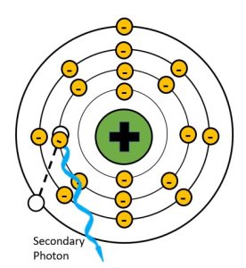
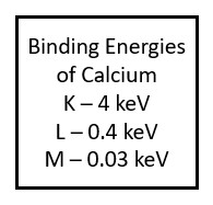
Because the atoms in the human body have much lower atomic numbers than we see in the x-ray tube, the characteristic x-rays produced have much lower energy. For example, calcium, which has one of the higher atomic numbers of the elements in the body, only has a k-shell binding energy of 4 keV. When an outer shell electron transitions to the k-shell, the secondary photon released will have an energy of just under 4 keV. Such low energy x-rays rarely make it out of the body, and only contribute to patient dose. When we add substances with higher atomic numbers to the body, like the barium sulfate or water-soluable iodine contrast agents, the secondary radiation can reach the image receptor. For example, the k-shell binding energy of iodine is 33 keV, which is in the same energy range as the majority of the x-rays produced by brems interactions in the tube. Because secondary radiation doesn’t originate from the same focal spot, it does not represent the anatomy like the x-rays in the primary beam do. When secondary x-rays do reach the image receptor they create fog, additional radiation exposure that veils or hides the radiographic image produced by the remnant beam. This reduces the visibility of the image and is undesirable.
Key Takeaways
Compton Scatter
A process first described by Arthur Compton in 1922, the Compton effect involves a collision between an incident x-ray photon and an outer shell electron. Compton interactions occur when the energy of the incident x-ray photon is MUCH higher than the binding energy of the orbital electron it collides with. The incident photon collides with the outer shell electron and transfers some of its energy to the electron. The orbital electron gains enough energy to break the bonds holding it to the nucleus and propel it away from the atom. The remaining energy is emitted from the atom as an x-ray. See Figure 2-9. We call the electron that is dislodged from the atom is called a Compton or recoil electron, and the x-ray that is emitted a Compton scattered photon. Because an electron has been removed, the atom is now an ion. The recoil electron continues along its path until it binds with another nearby atom creating another ion.
Figure 2-9: Compton Interactions
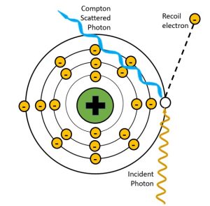
In the Compton effect, the incident x-ray photon is partially absorbed by an outer shell electron.
When the remaining energy is emitted from the atom as a Compton x-ray, it has lower energy than the incident photon and is traveling in a different direction. That is why we refer to it as “scatter.” The energy transfer can be described by the following mathematical equation:
 In this equation, Ei, the energy of the incident photon, is distributed between Eb, the binding energy of the orbital electron, Eke, the kinetic energy propelling the orbital electron away from the atom, and Es, the energy of the Compton scattered photon. Because the energy of the scattered photon is decreased in comparison to that of the incident photon, it also has a longer wavelength and lower frequency (this means the bumps made by the waves get further apart). The change seen in the energy of the scattered photon depends on the angle at which x-ray is deflected relative to the original trajectory. When the angle of deflection is larger, more energy is transferred to the electron and less energy continues as the scattered photon. The less the scattered photon changes direction, the more of the original energy it retains. See Figure 2-10. The incident x-ray can be deflected anywhere from 0 degrees to 180 degrees. When the change is closer to 0, the scattered photon moves in a forward direction and keeps most of the energy. When the change is closer to 180, the scattered photon bounces back the way the incident photon came and loses most of its energy.
Figure 2-10: Deflection Angles and Scattered Photon Energy
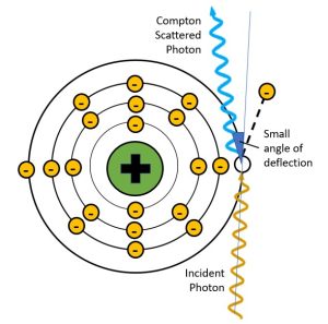
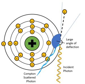
When the scattered photon has a small angle of deflection, it retains most of the energy of the incident photon. When the scattered photon’s angle of deflection is large, most of the energy from the incident photon is transferred to the electron and the scattered photon has much lower energy, much longer wavelength and much longer frequency.
The Compton scattered photon, or scatter for short, typically has high enough energy to reach the image receptor and cause destructive fogging of the image. Compton scattering is responsible for 99% of the fogging photons that reach the image. The fog created by scattered photons, like the fog created by secondary radiation, does not correspond to anatomical structures and covers the image in radiation exposure that covers up, or veils, the anatomical signal and reduces image contrast. Many of the exposure choices we make as radiographers are aimed at reducing the number of scattered photons before they reach the image receptor. It is convenient that the strategies to control scatter are also effective and reducing or eliminating secondary radiation.
Key Takeaways
General Principles of X-Ray Interactions
X-rays interact with lots of different things, both inside and outside the x-ray tube. As imaging professionals, we are primarily interested in how they interact with our patient and the image receptors so we can optimize the display image and minimize patient dose. Regardless of what structures we are imaging, the interactions are similar and are primarily affected by the average atomic number of the structure and the energy of the x-rays employed. Absorption is also influenced by the density of the tissue as well as its thickness.
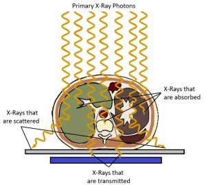
The x-rays in the primary beam creates the image signal in the following ways (See Figure 2-11):
- X-rays that interact through the photoelectric effect contribute to the image by blocking the x-rays. This leaves areas of low exposure (white areas) on the image that represent areas of greater attenuation in the patient’s body.
- X-rays that pass through, or are transmitted through, the body deposit energy onto the image receptor. This leaves areas of greater exposure (black areas) on the image that represent areas of lower attenuation in the patient’s body.
- X-rays that are scattered inside the patient’s body, change direction but may still reach the image receptor. Scattered x-rays deposit energy into the image receptor and leave areas of greater exposure (black areas) on the image. These areas of exposure do not represent the patient’s anatomy but cover the light and dark areas evenly, making it more difficult to see the parts of the image that actually represent the anatomy. The scattered photons may be referred to as a type of noise because they hinder the visibility of the signal.
This demonstrates that, while Compton scatter and the photoelectric effect are important, it is the x-rays that are transmitted through the body without interacting that carry the image information to the image receptor. Overall, the radiographic image results from the differences between the x-rays being absorbed by the photoelectric effect and the x-rays transmitted through the patient to the image receptor. The different degrees of x-ray absorption in different tissues that creates image contrast is described as differential absorption.
Figure 2-11: Differential Absorption and the Radiographic Image
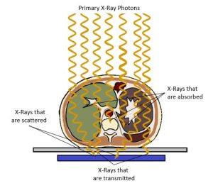
The x-rays in the primary beam creates the image signal when passing through the patient by:
- Photoelectrically absorbed x-rays leave areas of low exposure (white areas) on the image that represent areas of greater attenuation in the patient’s body.
- X-rays that pass through the body leave areas of greater exposure (black areas) on the image that represents areas of lower attenuation in the patient’s body.
- Scattered x-rays leave areas of greater exposure (black areas) on the image but contribute no useful information.
Differential Absorption
When x-rays pass through the body, each type of tissue absorbs the radiation in its own way. We refer to this difference in the number and type of radiation interactions between two tissues as differential absorption. The amount of radiation the tissue absorbs corresponds to the atomic number of the elements composing the tissue as well as the thickness of the tissue and its density. The atomic number of the elements that compose the tissue causes bone to absorb more x-rays than muscle or fat. Differential absorption is a key factor determining image contrast. Contrast is an idea that we will discuss throughout this book. Contrast is the number of black, white and gray tones seen in an image. It can also be defined as the difference in brightness between two adjacent areas of the image. Differential absorption and the subject contrast it creates is the primary reason we can tell the difference between different tissues within the same patients.
We also use differences in atomic number to make some structures more apparent by using contrast media. Contrast agents, which contain either barium (atomic number 56) or iodine (atomic number 53) enhance the visibility of certain anatomical structures because they contain atoms with higher atomic numbers than the surrounding tissues. The higher atomic number results in greater photoelectric interactions with the beam.
When we are comparing radiation absorption between patients, the tissue thickness and density comes into play. For example, muscle tissue is generally composed of the same elements for everyone, but a bodybuilder has thicker muscles and will absorb more radiation than the same body part of an individual who does not work out. Similarly, the measured thickness of the bodybuilder’s arm may be the same as the thickness of an obese person’s arm, but the muscle tissue is more dense than fat and, again, absorbs more x-rays. In this example we see that x-ray absorption cannot be predicted by thickness alone. We must take into consideration the individual’s physical state and the possible presence or absence of elements with higher atomic numbers. The absorption of x-rays by various tissue components introduces the idea of subject contrast, which is of major importance to the creation of the radiographic image.
Subject Contrast
We refer to the differences in x-ray absorption in different tissues as subject contrast. We use some special terms to talk about the relative differences in x-ray absorption. Tissues that produce a high amount of photoelectric interactions appear white on the image and are referred to as radiopaque. Bone is an excellent example of a radiopaque tissue. Tissues that allow the x-rays to pass through without interacting appear dark or black on the image and are referred to as radiolucent. Lung tissue is an excellent example of radiolucent tissue.
The combination of radiopaque and radiolucent structures lets us understand the patient’s anatomy. See Figure 2-9. In a typical chest x-ray we see several bony radiopaque structures including the spine, clavicle and ribs, but we also see the heart shadow as radiopaque because it absorbs more radiation than the surrounding lung tissue. The thoracic spine is more radiopaque than the heart, because we can see the individual vertebrae through the outline of the heart. We also see several radiolucent structures on a typical chest x-ray. These structures are typically filled with air. Because air is a gas, the atoms are not dense at all and do not block x-rays well. In figure 2-12, we see the lungs as radiolucent, but we also see the trachea filled with air, where it overlies the top portion of the thoracic spine. The air above the patient’s shoulders likewise appears dark on the image because there was nothing in the way of the x-ray beam for the photons to interact with.
Figure 2-12: Subject Contrast in a Chest X-Ray
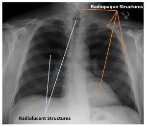
On a typical chest x-ray the spine, clavicles, ribs and heart appear radiopaque. The lungs and trachea appear radiolucent.
Activity 2B: The X-Ray Beam and its Interactions
Test your understanding of concepts related to the x-ray beam and its interactions with matter on this crossword puzzle.
LAB Exercise 2: Discovering Subject Contrast
Summary
Radiographic distances include the distance between the x-ray tube and the image receptor – SID, the distance between the object being radiographed and the image receptor – OID, and the distance between the x-ray tube and the object being radiographed – SOD. These distances can be calculated if you know 2 of the 3 factors.
Attenuation is the reduction in the number of x-ray photons in the beam as it travels through an object. Attenuation happens when x-rays in the beam interact with the matter it is passing through.
The two interactions between x-rays and matter that occur at diagnostic levels are Compton scattering and the photoelectric effect.
- In Compton scatter the incident x-ray photon interacts with an outer shell electron, ionizing the atom and redirecting the x-ray that has lost some of its energy. The electron ejected from the atom in a Compton interaction is called a recoil electron.
- In photoelectric effect, the incident x-ray photon interacts with an inner shell electron where it is completely absorbed in the process of ionizing the atom. The electron ejected from the atom in a photoelectric interaction is called a photoelectron.
Differential absorption is the differences seen the degree of absorption of the x-ray beam between different tissues. These differences in x-ray absorption are responsible for creating the radiographic image. Differential absorption occurs because of differences in:
- The atomic number of atoms in the tissue
- The x-ray energy
- The mass density of the tissue
- The thickness of the part
Contrast agents enhance the visibility of certain anatomical structures because they contain atoms with higher atomic numbers, and have higher mass density than the surrounding tissues.
We use variations in x-ray energy, primarily controlled by kVp, to vary the differential absorption, and subsequently the contrast of our images.
While we should consider the thickness of the part when selecting technical factors, we must also consider the make-up of the area in terms of tissue type and mass density.
The x-ray that is in the exact center of the x-ray beam.
The portion of the imaging chain that captures the x-ray signal for conversion into a visible image. Abbreviated "IR".
The object-image distance; the distance between the image receptor and the part inside the patient that is being examined.
The source-image distance; the distance from the x-ray tube to the image receptor.