9 Radiographic Angulations
The four radiographic qualities introduced in Ch. 4 are brightness, contrast, spatial resolution and distortion. We also need to emphasize image receptor exposure, as it plays a big role in overall image quality. As we have seen in Ch. 5 & 6, image receptor exposure and contrast are controlled by the quality and quantity of the photons in the beam and these are controlled by mAs and kVp. The other two radiographic qualities – spatial resolution and distortion are controlled by the geometric properties of image production. In Ch. 7, we learned about one geometric factor, focal spot size, and discovered that the only thing focal spot size affects is spatial resolution. In Ch. 8, we discussed how SID and OID affect IR exposure, size distortion and spatial resolution.
In this chapter you are going to learn about radiographic angulations, and their relationship to the IR exposure, patient dose and the four image properties. You will learn about the relationship of radiographic angulations to spatial resolution and distortion and how it impacts image quality.
Learning Objectives
At the end of this chapter, you should be able to:
- Define shape distortion and explain how it differs from size distortion.
- List the three types of shape distortion.
- Differentiate between the x-ray beam and the central ray.
- Define the term object.
- Describe the ideal relationship between the central ray, object and image receptor that will produce the least amount of distortion.
- Describe how foreshortening occurs.
- Explain how foreshortening of the image can be avoided when the object is at an angle in relation to the image receptor.
- Describe how elongation occurs.
- Explain why it is important that the central ray be placed directly over the structures of interest.
- Explain how elongation can be used to the radiographer’s advantage.
- Describe superimposition.
- Describe how spatial distortion occurs.
- Explain the importance of the direction of the central ray when using spatial distortion to improve the image.
Shape Distortion
We learned about size distortion, which is also called magnification. Size distortion occurs when the image is larger than the actual size of the object. The cause of size distortion is a long OID or a short SID.
Size distortion is only one part of the problem of distortion. Another type of distortion is called shape distortion. When shape distortion occurs, the image appears to be a different shape when compared to the actual shape of the object. The image could appear stretched out of shape or squished together when compared with the object.
There are three types of shape distortion: foreshortening, elongation and spatial distortion. Shape distortion isn’t always a bad thing. Elongation and spatial distortion are sometimes used intentionally to enhance the appearance of a body part on the radiograph.
Types of Shape Distortion
Shape distortion is defined as the misrepresentation by the image of the true shape of the object. There are three types of shape distortion. The first type is called foreshortening. In foreshortening the image appears squished together. On a radiograph with foreshortening a bone appears to be shorter and thicker than it actually is.
Another type of shape distortion is called elongation. In elongation the image appears stretched out when it is compared to the object. On the radiograph an elongated bone appears longer and skinnier than it actually is.
The third type of shape distortion is called spatial distortion. In spatial distortion, there is a misrepresentation of the three-dimensional relationship of the structures within the body part being examined. On the radiograph, body parts may appear separated when they are not separated in the actual body.
Shape distortion occurs when the relationship of the direction of the x-ray beam, the position of the image receptor, and the position of the part varies somehow from what is considered ideal.
Key Takeaways
Shape distortion is the misrepresentation by the image of the true shape of the object. There are 3 types of shape distortion:
- Foreshortening – the image appears shorter and fatter than the object.
- Elongation – the image appears longer and skinnier than the object.
- Spatial Distortion – the three-dimensional relationships of the object are misrepresented, for example, appearing dislocated when the joint is actually in correct alignment.
The Ideal Relationship
To produce the least amount of shape distortion, the radiographer needs to use the ideal relationship between the positions of the x-ray beam or central ray, the image receptor and the object.
The Central ray
Because of the collimation that the x-ray beam passes through as it exits the tube housing, the x-ray beam that is directed at the patient is pyramid shaped. If the beam is directed straight at the patient’s body, the photons at the edge of the pyramid of radiation hit the patient’s body at an angle. The photons in the center of the beam would be perpendicular to the body. The photon in the exact center of the beam is called the central ray. See Figure 8-6. The angle of the x-ray beam is always measured at the central ray rather than at the edges of the beam.
Figure 8-6: The Pyramid – Shaped X-Ray Beam
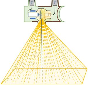
The x-ray beam is pyramid shaped. The photons diverge away from the central ray (blue) that is perpendicular to the part so that the photons at the edge of the beam enter the patient at an angle.
X-ray tubes can usually be angled 360 degrees, but most tubes have a stop or detent, which lets the radiographer know when the tube is positioned so the central ray is perpendicular to the bucky tray or the x-ray table top. The tube can also have a stop to let the radiographer know when the central ray is exactly horizontal for upright or cross-table lateral radiography. The stops are there so that the central ray isn’t accidentally at an angle when it is supposed to be perpendicular to the image receptor.
The Image Receptor
The image is recorded on the image receptor. The image receptor is placed where the radiation will exit from the patient’s body. The image receptor can be placed in several different locations depending on how the patient is being positioned. Sometimes the image receptor is placed in the bucky tray, which is located just under the x-ray table top. The image receptor could also be placed on the table top, or in the upright bucky. The image receptor is sometimes placed directly under the patient’s body. some of these locations are more prone to producing shape distortion than others.
The Object
The object is the body part that the radiographer is trying to image on the radiograph. The radiographer may be trying to produce an image of a whole sections of the patient’s body, such as the abdomen, or just one part inside the abdomen. If the area of interest is just one part of the abdomen like the kidney, then that part is referred to as the object.
Producing the Ideal Relationship
The ideal relationship is produced by placing the object parallel to the image receptor, the central ray perpendicular to the object, and the central ray perpendicular to the image receptor. The central ray should also be placed over the center of the object. See Figure 8-6.
Figure 8-6: The Ideal Relationship
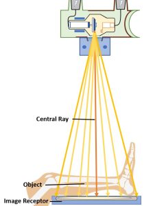
The ideal relationship:
- Object parallel to image receptor
- Central ray perpendicular to part and image receptor
- Central ray centered to the part and image receptor
Variations from the ideal relationship can product the three types of shape distortion: foreshortening, elongation, and spatial distortion.
Foreshortening
Foreshortening occurs when the object is at an angle and the central ray is perpendicular to the image receptor. See Figure 8-7. With foreshortening the image will appear squished together when compared to the object, like a car that was tin the middle of a three-car wreck. Minuet detail in the object may not be seen on the image.
Figure 8-7: Foreshortening
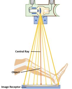
In foreshortening, the central ray is perpendicular to the image receptor, but the object is angled.
Foreshortening produces an unequal amount of magnification of the parts of the object. With a tilt or angle of the object in relation to the image receptor, each part of the object will lie at a different object-image distance (OID), so each part will be magnified a different amount on the image.
If a radiograph is taken of a fractured bone, the radiologist needs to be able to tell how far apart the broken bone fragments are. The fracture space can be seen well on an image taken with the ideal central ray, object and image receptor relationship. If the image is foreshortened, the radiologist will be unable to judge the space between the fracture fragments correctly. If the fracture is very small, it can even be hidden in a foreshortened image.
In clinical situations where it is impossible to achieve the ideal central ray, object and image receptor relationship, the body part may lie at an angle to the central ray and image receptor, and the image would b e foreshortened. In this case the radiographer can sometimes avoid a foreshortened image by turning or angling the x-ray tube so the central ray will be perpendicular to the object. Placing the central ray perpendicular to the object helps to improve the image even if the central ray is not also perpendicular to the image receptor. The image will appear less foreshortened because some elongation occurs since the central ray is perpendicular to the object but not the image receptor.
Elongation
Elongation is a type of distortion that occurs when the object is parallel to the image receptor but the central ray is angled. See Figure 8- 8. Elongation can also occur if the central ray is perpendicular to the object but the object is not parallel to the image receptor. With elongation, the image appears stretched out of shape when compared with the object, like a piece of taffy pulled from both ends.
Figure 8-8: Elongation
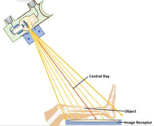
In elongation, the object is parallel to the image receptor, but the central ray is angled.
Although elongation can produce shape distortion in the image, sometimes this shape distortion can actually help the radiographer image body parts that would ordinarily be superimposed. A good example of this is the axial view of the sigmoid colon taken during a barium enema.
The sigmoid colon, which is near the rectum, is S-shaped and twists around in the body. If a radiograph is taken during a barium enema with the patient lying flat on the x-ray table and the central ray perpendicular to the image receptor, the parts of the sigmoid colon will superimpose each other in the image. If the radiographer angles the central ray, the sigmoid colon will appear elongated on the image. The twisted parts of the sigmoid colon will then be seen separated on the image, without superimposition.
Beam Centering
Another consideration with elongation concerns divergent rays. Because the x-ray beam is pyramid-shaped, when the beam is directed straight at the patient’s body, the photons at the edge of the beam are at a slight angle compared with the photons at the center of the beam. Therefore, on every radiograph, especially ones on a large image receptor, there is some elongation of the image at the edges of the image receptor. Because of this it is important to keep the structure of interest directly under the central ray to avoid the slight elongation that may occur if the structure is placed at the edge of the beam. This is especially important when the joint space is required to be open on the radiograph.
Key Takeaways
Spatial Distortion
Spatial distortion occurs when the central ray is at an angle, but the object and image receptor are parallel to each other. In spatial distortion the three-dimensional relationship between several body parts is distorted on the image by different elongation of each part.
If two body parts lie on top of each other in the image, they are superimposed. If the radiographer is taking a radiograph of the whole abdomen, with the patient lying on the table face up, the x-ray photons from a perpendicular beam would enter the patient’s abdomen in the front, go through the entire abdomen, and exit from the back. The photons would then enter the image receptor, which is where the image is formed. Because the image is two-dimensional, the contents of the entire abdomen appear to be on top of each other. This is called superimposition. See Figure 8-9.
Figure 8-9: Superimposition
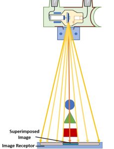
Superimposition of the circle, triangle and square.
If a radiographer were trying to produce an image of the right kidney, the ribs, liver and fat may be seen on the image of the kidney. If several body parts are superimposed in the image, none of these parts is seen clearly as individual structures. sometimes this is not a problem, but when it is necessary to avoid superimposition, the radiographer can either turn the patient’s body so the parts will be separated and not superimposed, or angle the x-ray beam. Angling the beam produces spatial distortion.
If the central ray is directed at an angle to two body parts that lie on top of each other in the body, but at different distances from the image receptor, the two body parts would not be superimposed but would appear separated on the image. Both body parts would be elongated, but the object with the largest OID would be more elongated. This part will lie in a different spot on the image than the part with a shorter OID. Thus, on the image it would appear as though the two parts were not actually on top of each other in the patient. The two parts would be spatially distorted on the image. See Figure 8-10.
Figure 8-10: Spatial Distortion
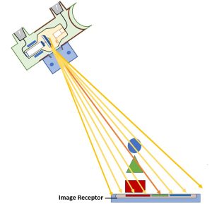
In spatial distortion the three-dimensional relationship of body parts is distorted by an angle of the central ray.
Spatial distortion can be used to the radiographer’s advantage. A good example is the problem of trying to see the clavicle as a separate structure on the image. The clavicle is located in the superior aspect of the chest. If a radiograph is taken of this area with the patient flat on the table face up and the central ray perpendicular to the image receptor, the clavicle will appear superimposed over the top of the chest on the radiograph. A small fracture of the clavicle might be hidden by this superimposition. By angling the central ray toward the patient’s head, the clavicle, which has a longer OID than the chest, appears above the chest on the radiograph, and it is seen as a separate structure.
The direction of the angle of the central ray is important when the radiographer is trying to use spatial distortion to separate structures. In the above example, with and angle of the central ray toward the patient’s head, the clavicle appears above the chest on the radiograph. It is seen higher that it really is in the body. With an angle of the central ray toward the patient’s feet, the clavicle will be projected lower in the patient’s chest than it really is in the body. This would superimpose the clavicle over the middle part of the chest and would not improve the image of the clavicle.
Key Takeaways
Summary
The ideal relationship between the central ray, object and image receptor produces the least shape distortion. The central ray should be placed directly over the structure of interest. The central ray should be positioned perpendicular to the object and to the image receptor. The object and image receptor should be parallel to each other.
Foreshortening occurs when the object is at an angle, but the central ray is kept perpendicular to the image receptor. Elongation occurs when the object is parallel to the image receptor, but the central ray is angled. Spatial distortion occurs when two objects would normally appear superimposed in the image but appear as separate structures due to an angle of the central ray.